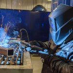
Bernard Expands and Updates Clean Air Fume Extraction Gun Offering
BEECHER, Ill. November 16, 2017 — Bernard has introduced a new model to the Clean Air™ fume extraction gun family and has updated the entire Clean Air offering with a new look. A 300 amp MIG gun has been added to the Clean Air family, which allows users to reduce smoke at the source with an industrial-duty fume extraction gun that is comparable in size and weight to a regular welding gun. In addition, Bernard has changed the finish from chrome to black on all Clean Air fume extraction gun vacuum tubes and chambers. This aesthetic change has been made on all new guns, replacement vacuum tubes and replacement chambers.

The expansion of the Clean Air fume extraction gun offering provides more choices and greater flexibility for operations seeking to establish a cleaner, more compliant work environment. Clean Air fume extraction guns are also available in 400-, 500- and 600-amp models and can be used with solid and flux-cored wire. The guns are compatible with high performance consumables from Bernard, including Centerfire™, Quik Tip™ and TOUGH LOCK®, as well as the conventional liner or QUICK LOAD® liner. Users can make their selection and customize their Clean Air fume extraction gun when configuring their gun online.
All Clean Air fume extraction guns have a small vacuum chamber that provides good joint access and visibility, along with a 360-degree vacuum hose swivel on the rear of the handle that improves flexibility and reduces operator wrist fatigue. The guns are ideal for large weldment and confined space welding applications.
Companies invest in robotic welding systems to improve productivity and gain efficiencies in their operation. But if the weld cell layout is not optimized, it can negatively impact those goals — along with the quality of the completed welds. Poor cell layout can create a bottleneck in the process or result in parts not being properly welded —problems that cost time and money in the long term. When considering proper layout for a robotic weld cell — whether it’s a pre-engineered cell or a custom cell —gun and consumable selection, robot reach, parts flow in and out of the cell, and weld sequencing are all important. Proper weld cell layout is important for both pre-engineered robotic welding systems or a custom-designed system. Determining which option is right hinges on several factors. A pre-engineered robotic welding cell is designed for welding specific parts in a certain size range. Pre-engineered cells offer benefits for easy and fast installation and a much lower first cost, but they do have their limitations regarding the type and size of parts that can be welded. Part size is often the key determining factor when choosing between the two systems. If there isn’t a pre-engineered weld cell available to fit the parts — perhaps there is a reach or weight capacity issue — then a custom robotic weld cell is the better option. Custom cells have a higher initial cost and typically a longer lead time for design and installation, but the upside is they can be customized to meet specific needs. When installing either type of robotic weld cell, the system integrator should be involved in planning and testing to ensure cell layout is optimized for the application. Having the right gun is a critical factor that can help reduce or eliminate the sources of common problems in the weld cell. Gun choice should not be an afterthought in robotic welding applications. The gun must have proper access and be able to maneuver around fixturing in the weld cell. Different choices in gun types and in consumables can help in achieving this. Robotic welding systems are available in two styles: through-arm or conventional. Through-arm systems are gaining popularity, and most through-arm robots allow for mounting either type of gun — providing more options and flexibility depending upon the needs of the application. As the name suggests, the power cable assembly of a through-arm MIG gun runs through the arm of the robot as opposed to over the top of it like in a conventional gun. Because of this design, the through-arm gun style is often more durable, since the power cable is protected. However, because conventional guns can be used on either type of system — a through-arm or a conventional robot — they can sometimes offer greater flexibility, and can be used with more robot makes and models. Consider which type of gun provides the best access to the welds when making the selection. With conventional robotic welding systems especially, proper cable management is important. Once the hardware is installed and the system is set up — but before full production begins — be sure to do a test run or two through the welding sequence to determine how the gun cable moves and if it gets caught on tooling. Another choice in selecting a gun is air-cooled versus water-cooled. This essentially comes down to the required duty cycle. The base material thickness, weld length and wire size all help determine the necessary duty cycle. Water-cooled guns are typically used in manufacturing heavy equipment and in the case of long cycle times and large wire diameters. Once the system type and gun is chosen, it’s all about proper fit and function of the gun. It’s critical to ensure the robot arm can access all the welds — ideally in one position with one neck if possible. If not, different neck sizes, lengths and angles — and even custom necks — as well as different consumables or mounting arms can be used to improve weld access. The choice of nozzle is another important consideration, since it can greatly hinder or improve access to the weld in a robotic cell. If a standard nozzle is not providing the necessary access, consider making a change. Nozzles are available in varying diameters, lengths and tapers to improve joint access. While many companies like to choose a nozzle with the smallest outside diameter available, it may be necessary to size the nozzle up to avoid spatter buildup and loss of shielding gas coverage. A nozzle with a 5/8-inch bore or larger is recommended because it allows the most access. Choosing the right gun is tied closely to proper weld cell layout — since different sizes and lengths of guns and nozzles can improve or hinder reach to the welds. However, there are also many other factors involved in proper weld cell layout. Think of weld cell layout as the footprint of the entire process. Some important issues to keep in mind: Weld cell layout and the chosen components that fit inside have a significant impact on productivity, efficiency and quality of the finished welds. Weld cell layout that is not optimized can even harm the tooling or consumables, and result in increased time and money spent on maintenance and repair. Protect the robotic weld cell investment by taking the time at the start of the process to test proper cell layout and equipment — to help ensure the end results and productivity gains being sought. Changing a conventional liner can cost you in more ways than one. The Tregaskiss QUICK LOAD liner AutoLength system can help you eliminate those costs.
The fabrication and manufacturing industries continue to experience demands for greater productivity, increased efficiencies and higher cost savings — often times with less labor to support the efforts. Every improvement companies can make to achieve these goals is beneficial, from offering more operator training to implementing lean practices. Managing MIG guns and consumables that meet the needs of multiple applications is also an important element in achieving those goals, both from an inventory perspective and as a matter of eliminating unnecessary downtime. There are rarely, if ever, welding operations that require only one type of MIG gun or a single consumable. In fact, it’s not uncommon for many companies to have multiple MIG guns and consumables in use as a routine part of their daily operations, especially within the automotive manufacturing and pressure vessel industries. Automakers, for example, often have handheld and automation weld cells all in the same building. Similarly, welding operators working on different-sized pressure vessels may have a 1,500 gallon tank being welded together with a larger, higher-amperage MIG gun, while welding operators are fabricating a smaller tank nearby with much smaller, lighter-duty MIG gun. Understanding how to pair the best gun and consumable with the job can pay off in workflow and cost savings, and help improve the quality of completed welds. In addition, minimizing the part numbers for MIG guns and consumables can simplify inventory, which ultimately saves time for management and saves storage space. It can save time during the welding process, too. In the shipbuilding industry, for instance, welding operators move around frequently so they do not have the capacity to swap out MIG guns to address multiple applications. Instead, they often standardize on one type of MIG gun and swap out the necks, installed with a jump liner that replaces the front part of the liner system (the rest seats in the power cable). Doing so allows them to keep the same gun for the job, while gaining access to a new joint with the appropriate neck length or configuration. Below are five tips to help streamline welding operations and remain competitive by managing MIG guns and consumables effectively. Using fewer power cable lengths throughout an operation is possible when there is a difference of two or three feet between each application. For example, it may be possible to standardize on a 15-foot cable for weld cells that need this or a slightly shorter length — without causing issues with kinking of poor wire feeding. Doing so minimizes inventory and storage space requirements. It also takes away the guesswork when it comes to replacing this part of the MIG gun, as it eliminates the risk that a welding operator or maintenance employee will install the wrong length power cable on a MIG gun. 2. Choose one type of liner, when possible. There are different styles of liners available for MIG guns, including steel liners, D-wound liners or Teflon® liners. Teflon liners are well-suited for wires that are difficult to feed, including stainless steel or aluminum. Standardizing liner types across multiple weld cells, when possible, can reduce downtime for changeover and costs for inventory. Always make sure the liner is properly installed; otherwise, problems like birdnesting and feeding issues can result. 3. Use the same contact tips, even across semi-automatic and robotic weld cells. Use one type of contact tip across applications whenever possible. For companies that have both robotic and semi-automatic welding operations, common consumables can be especially helpful to streamline processes and inventory — while also reducing costs. It is not uncommon in robotic welding applications for welding operators to change contact tips long before they become worn, as it helps ensure that there is minimal downtime for problems associated with failures. These contact tips, however, still have life in them and can be used on semi-automatic MIG guns to reduce part numbers and count in inventory, and overall costs. It can also reduce confusion as to which contact tips to use across the welding operations. Too many different types of contact tips, for instance, can be confusing and can lead to a welding operator using the wrong parts on the wrong MIG guns. That misstep can bring production to a slowdown or a halt. 4. Adapt the power pin. It is not uncommon for companies to have multiple types and brands of power feeders throughout the welding operation. When possible, standardizing the power pin used in every MIG gun, via an adaptor at the feeder, can help streamline the management of various power pins to match these feeders. If a company also has various types or brands of MIG guns, an adapter can also help with gun standardization. The guns can be ordered with the same power pin and plugged into any wire feeder throughout the facility, again streamlining ordering and inventory, and minimizing costs. 5. Review MIG gun amperage and select one to streamline. In some instances, it may be possible to use the same amperage of MIG gun for multiple applications. For example, if 200 amp and 300 amp guns are both part of the inventory, using 300 amp guns in each cell can make it easier to manage inventory. It can also help prevent the potential for overheating if a smaller gun is accidentally used in place of a larger, higher-amperage one for a higher duty cycle job.
The Consumable Challenge proves a welder can change Bernard Centerfire consumables on a BTB MIG Gun faster than competitor consumables. Watch as we compare the strength of our Bernard BTB semi-automatic air-cooled MIG gun handle to those of our competitors. Watch as we compare the in real-time how long it takes to replace a QUICK LOAD liner VS. conventional rear-loading liner.
“Graham Corporation serves petrochemical refining markets, some food services. We’re a complete corporation from engineering all the way through manufacturing. I feel that you’re never going to get any rewards without effort and change is part of those rewards. You have to be willing to make those changes and pursue them. When we bought the Pipeworks we found out that we like the Bernard guns that came with it. The ease of operation, durability, the change overs and we just felt it was a good fit for the plant as a whole. We thought it would be to our advantage to have just one consumable for all our guns.” Watch to learn more about what Graham Corporation has to say about Bernard MIG guns and consumables. A robotic MIG welding system contains many components that impact the quality of the parts it welds, its productivity and the overall operational costs. Among those, the robotic MIG gun neck plays a larger role than may first be apparent. Why? The durability of the gun neck — and especially its ability to withstand impacts — is important for maintaining tool center point (TCP). An accurate TCP provides consistency and repeatability from part to part, and is key to the system’s ability to maintain weld positions, especially in assembly line welding where new parts are continually entering the weld cell. A productive and efficient robotic welding system places welds in the same place every time. To achieve this, the MIG gun neck needs to stay in its expected position. A weak neck that easily bends during routine welding can lead to TCP problems over time, as can rough handling of the neck during consumable changeover. Issues with TCP can lead to additional spatter or missed welds, causing rework or scrapped parts. These cost time and money in lost productivity and in wasted parts. An inaccurate TCP can also cause the neck to crash into parts or tooling, potentially leading to damage and unplanned downtime. When selecting a robotic MIG gun neck, look for durable, high quality materials and robust construction. The goal is to have a neck that is strong enough to withstand minor crashes without bending. In addition, be certain there is a solid connection from the neck to the gun, and from the gun to the mounting arm in a conventional system or to the robot itself in a through-arm system. Any play in the system can negatively impact TCP. Neck durability varies, depending on if the application uses an air-cooled or a water-cooled robotic MIG gun. Some applications require water-cooled guns to protect the gun and the neck in high-temperature continuous welding; however, these guns tend to be less durable in a crash than air-cooled gun necks due to the internal soldering of copper and brass lines for the water passages. Air-cooled guns typically feature copper tubes covered with insulation and aluminum, making them stronger and more able to resist an impact. Some manufacturers offer a hybrid air/water-cooled robotic MIG gun, in which the water lines run external to the neck. This type of gun tends to have a stronger neck, like an air-cooled gun, which makes it more tolerant to crashes. However, it is important to ensure the water lines do not hit tooling or parts, which can negatively affect TCP or create leaks. Some key best practices can help protect the neck and provide consistent TCP: All robotic welding systems require a form of collision detection to prevent damage to both the robotic MIG gun and the robot arm in the event of an impact. Some robotic systems incorporate robot collision detection software. Systems that do not have built-in collision detection should always be paired with a clutch — an electronic component that attaches to the gun to protect it and the robot from heavy damage in the event of a collision. Another key peripheral is a neck inspection fixture, which verifies that the gun’s neck is set to the intended TCP and allows the neck to be readjusted after a collision or if it becomes bent during routine welding. If neck adjustment is needed, the welding operator simply adjusts the neck to meet the proper specifications. This prevents costly rework due to missed weld joints and can reduce downtime to reprogram the robot to meet the welding specifications with a bent neck. Having spare necks ready helps gets the system back online quickly. The welding operator need only remove the bent neck in the event of a crash and exchange it with a spare one. The damaged neck can be set aside for inspection later, minimizing interruption to the weld cycle. Choose a high-quality reamer to avoid potential damage to the gun or neck. A reamer, or nozzle cleaning station, removes spatter from the nozzle and clears away the debris that accumulates in the diffuser during welding. A high-quality reamer securely holds the gun in place during the ream cycle, which reduces the risk of bending the neck and compromising TCP. 5. Proper neck and consumable installation and ongoing maintenance are important. Make sure to tighten these components to factory specifications. When changing consumables, remove them with the right tools to avoid bending the gun neck. In many cases, a robotic welding system can provide a competitive edge — offering greater productivity, quality and cost savings. Take care to protect the MIG gun neck, and follow best practices for setup and maintenance, to help ensure the system maintains optimal TCP and the operation experiences minimal downtime.
The liners used in a robotic gas metal arc welding (GMAW) gun play a significant role in the productivity, cost and quality in your automated welding operation, alongside other consumables such as the nozzle, retaining head (or gas diffuser) and contact tip. Liners run the length of the robotic welding gun and power cable — from the contact tip to the power pin — and act as the conduit through which the wire is fed. A poorly installed liner can lead to problems with bird-nesting and excessive debris in the liner, which can both cause wire feeding issues that lead to downtime — the enemy of any robotic welding operation. For this reason, it is imperative to select the right liner for the wire type and diameter being used and to trim it to the proper length.
BEECHER, Ill. August 14, 2017 – Bernard and Tregaskiss will showcase its welding guns and consumables at FABTECH 2017 in Chicago, November 6 to 9, along with providing a variety of demonstrations. Both companies will share booth B23034 with Miller Electric Mfg. Co. and Hobart, where they will feature live welding demonstrations of Bernard semi-automatic and Tregaskiss robotic MIG guns with Miller power sources and robotic welding equipment using Hobart filler metals — offering visitors the chance to try a complete welding solution from the brands. In addition, representatives will provide demonstrations on how to repair, maintain and install option changes to the Bernard BTB semi-automatic air-cooled MIG guns, to illustrate the ease of maintenance or modification. The company plans to feature new products designed to improve quality, productivity and cost savings, and will have representatives available to answer product and technology questions.
In robotic MIG welding applications, minimizing downtime is key. It reduces costs and improves efficiencies to help an operation meet its production goals. Gaining the best performance, in part, depends on the equipment being used. Having the right robotic MIG gun and power cable, for example, is critical. There are several factors to consider when determining the right gun style and cable length for the application. Prioritizing these are important, as using the wrong length cable can cause problems ranging from premature cable failure to poor wire feeding. Before selecting the power cable length, first consider whether a conventional gun or a through-arm robotic gun is best-suited for the application. Each style has its advantages and limitations. Through-arm robotic welding systems have become more common, as more equipment manufacturers develop this style compared to conventional robots. Through-arm robotic welding systems, however, allow for the mounting of either a through-arm gun or a conventional one. In some applications, the latter is the better choice. When choosing between the two, consider the available space and weld cell layout, joint access and the type of material being welded. Conventional guns can often access joints better and/or maneuver around tooling or fixturing that a through-arm gun can’t reach. Conventional guns can also be less expensive and faster to install, although they do require proper cable management. They also require more space, so they aren’t typically the best choice in smaller weld cells. Through-arm guns work well in applications where deep access to the part or fixture is necessary. Since they don’t have a mounting arm and take up less space, they also offer advantages in smaller weld cells. The design of the gun —with the power cable assembly running through the arm of the robot —manages excess cable slack, which typically helps them last longer than a conventional power cable. Selecting the proper cable length is critical for both types of guns and numerous factors impact the choice. These include wire feeder, the make and model of the robot, and robot articulation. Having the right cable length helps prevent problems with wire feeding that can lead to downtime and unnecessary labor and/or part costs to address the issue. The wrong cable can further increase costs and downtime due to premature cable failure. When using a conventional gun, a cable that is too short causes tension, which can result in components prematurely breaking down in the cable assembly. It can also cause the clutch or the robot to overload, which will send a collision detection signal that stops the robot — resulting in unnecessary downtime. A cable that is too long is also a problem, because it can get caught on tooling or result in extra weight that bogs down the mounting arm – potentially overloading the clutch. With a through-arm gun, a too-short cable with visible tension also causes problems. Choose a cable that allows some slack for the robot arm to move around. But remember, too much slack can be as problematic as too little slack. When choosing proper cable length for a through-arm gun, it’s important to know the robot make and model, the feeder make and model, and the measurements of the system. If any nonstandard equipment or tooling is mounted to the face of the robot, such as a gripper or a camera, this changes the thickness of the plate and therefore impacts the necessary cable length, requiring it to be longer. It is also important to know where the wire feeder is mounted relative to the robot casting to ensure proper cable length. Much of the same information is needed in choosing the right cable length for a conventional gun: robot make and model, feeder make and model. In addition, consider where the feeder is mounted on the robot or even remotely, as both will affect cable length. For both types of guns, the feeder should be adjusted each time the cable is replaced to manage cable slack properly. Failing to properly adjust the wire feeder can result in a cable that is too tight or long for the given application, causing premature failure and potential damage to the robot or wire feeder. Fixing these issues at the start of the process can help avoid much greater downtime and costs later. Following some best practices can help extend power cable life, reduce downtime and improve productivity. Many of the best practices are related to the programming of the automated welding system. Oftentimes, cables fail because they were set up to fail — the system is asking too much of the cable. Make sure the robot doesn’t articulate too far in either direction, to avoid placing excess stress on the cable, whether it is a conventional or through-arm robotic gun. It’s also important to limit the movements of axis five (bending) and axis six (rotation) to help extend cable life. The joints of the robot get smaller as they move from the base to the wrist. Use the larger joints nearer to the base as much as possible and rely on the smaller joints only when necessary to reach the weldment. In addition, employ a cable management system when using a conventional gun to ensure there isn’t too much slack in the cable. With too much slack, the cable will rub on anything around it and possibly catch on fixturing. When a robot moves at production speed, it can break the cable or fixture. Cable management systems can take the form of a recoil with an adjustment knob and pulley that allows the maintenance personnel or welding operator to adjust the position (length) and tension of the power cable. When using a through-arm gun, choose a rotating power cable connection to reduce the stress on the system. Conventional style unicables typically come with a crimped or solid connection, which limits rotational capabilities and produces torsional stress on the cable. Unlike conventional unicables, a power cable that incorporates a rotating power connection allows for stress-free rotation — and can ensure a longer cable life. Without the right equipment — and proper system programming — downtime can cost significant time and money in robotic welding applications. Take care upfront to choose the right equipment, including the gun and power cable, to save time and money in the long run and keep the operation running smoothly.
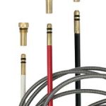
When choosing the right MIG gun for a semi-automatic welding application, there are many factors to consider — from the material being welded and the filler metal type to the weld cell layout and expected arc-on time. Customizing a MIG gun for the specific needs of the application, in addition to choosing the proper consumables, can pay off in greater productivity, better comfort and improved quality in the completed welds. There are easy-to-use tools, such as online configurators, available to help users customize a MIG gun. In addition, keep some key factors in mind to help configure a gun that best suits the application needs. Customizing a MIG gun offers numerous benefits compared to using a standard gun out of the box. Customization can maximize efficiency and productivity in a welding operation, and provide greater comfort. These can improve safety and offer longer arc-on time. Essentially, customization ensures that the welding operator has the exact MIG gun for the application. Also, some standard MIG guns may require extra time for assembly right out of the box. Some guns may also require extra components be added before welding can begin. This is not the case with customized MIG guns, which are ready for welding immediately. Customizing a MIG gun is like a pre-emptive strike against issues or challenges that otherwise would add time and money to a welding operation. To choose or customize the right MIG gun, look at several aspects of the welding operation. Like a decision tree, one answer impacts the next choice. First, consider the type and thickness of the base material, since both impact the filler metal selection. Once the material and filler metal are known, these dictate the welding parameters for the application. Understanding the welding parameters is important because the gun selected must meet the amperage and voltage requirements. While it’s important to choose a gun with enough amperage for the job, the larger the gun, the heavier it is, which impacts operator comfort. Next, think about the expected arc-on time and length of the welds. In addition to impacting the necessary amperage of the gun, these factors also play a role in ergonomics. For example, what length of gun is best for the physical space and length of the welds, and what handle style does the operator prefer? These factors come together in building the right gun for the job. The physical space of the welding cell is also an important factor. If there are fixtures or jigs to work around, consider these when configuring the gun and selecting consumables. For example, space limitations in the welding cell can impact cable length — the goal is always to have the shortest cable possible that still meets the needs of the application to avoid unnecessary coiling. The length and bend angle of the gun neck are also factors based on the available workspace and joint access. Remember, it is easier to make design choices like these up front rather than make changes to the gun after it’s purchased. Also consider if the application requires table welding or out-of-position welds. For flat welds at a table, the operator may repeat the same motion over and over. In this case, comfort and repeatability is key and a gun with a shorter cable can likely be used, which helps reduce overall weight. For out-of-position welds, the operator may need to move around a lot to complete the welds. Choosing a longer cable is helpful. Be aware, however, that a cable that is too long can be a tripping hazard for the operator or it can curl and tangle, causing wire feeding issues. There are two main options when choosing a MIG gun cable: steel mono-coil or industrial-grade cables. Industrial-grade cables are more commonly used. Steel mono-coil cables are well-suited for heavy-duty applications in harsh environments. These cables offer more rigidity and support to minimize feeding issues in applications where the wire must travel through a longer cable. Steel mono-coil cables are also used in applications where there is a risk they may get run over by equipment, such as a forklift. Cable lengths can vary greatly — from 10 feet to 25 feet or longer. While a longer cable may be necessary in applications that require the operator to move around, again, try to use the shortest cable possible that will get the job done. Smaller filler metal wire sizes typically call for a shorter cable, since it’s more difficult to push a smaller wire over a greater length. As wire size increases, the cable length can also increase. Deciding the best gun neck and handle choices for the application depends on several factors. These include operator preference and comfort, as well as weld cell space limitations or fixtures. The type of filler metal being used also plays a role. For example, necks with less bend reduce the chances for bird-nesting or other feeding issues with thicker wires and softer wires. Neck options are available with bends ranging from 30 degrees up to 80 degrees for applications where an extreme angle is needed to reach the weld joint. The choice of neck angle is often tied to the style of gun handle being used. Gun handles are available in straight or curved options, and the decision typically comes down to operator preference. For a straight-handled gun, a neck with a 60-degree bend is a frequent choice. Pairing a curved-handled gun with a 45-degree neck is another popular combination. Gun necks are also available in fixed or rotatable options. A rotatable neck makes it easier for the operator to change angles to access the weld joint without having to change out the gun. Straight handles are often paired with fixed necks, while curved handles are often paired with rotatable necks. Other features, such as trigger locking on the handle, which eliminates the need to hold the trigger during welding and increases comfort, can also be added when choosing the gun neck and handle. The bottom line: Choose the option that makes it easiest and most comfortable for the operator to reach the weld joint. Some MIG gun configuration tools also allow users to choose specific styles or types of consumables. Consumables must be able to handle the amperage of the application; some higher amperage applications may require heavy-duty consumables. Inventory management may be another factor — selecting the same consumables across multiple weld cells, when possible, is typically more convenient and cost-effective. The three key consumables to consider are contact tips, nozzles and liners. Consider the challenges or needs of a specific welding application — and the preferences of the welding operator — when selecting the right MIG gun for the job. A customized MIG gun can improve operator comfort, extend the longevity of consumables and offer greater productivity and efficiency in the operation.
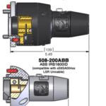
July 24, 2017 As of December 31, 2017, legacy TOUGH GUN® ThruArm® G1 series product for ABB® IRB1600ID configurations will be discontinued, and effective immediately, lead time for part number 508-200ABB will be 15 days. Our legacy TOUGH GUN ThruArm G1 series was replaced by our TOUGH GUN TA3 series in 2014, but although A58G1S connector housing is the replacement for 508-200ABB connector housing, this unit will change tool center point (TCP) by approximately 1.428″. For those customers using a 508-200ABB with a 405-22QC neck, we will be able to develop a special 22-degree neck for use with the A58G1S module to match their existing TCP. However, due to a length restriction in manufacturing, we will not be able to match TCP for those customers using a 508-200ABB with a 405-45QC neck. In this case, reprogramming will be necessary when switching to an A58G1S. Additionally, when transitioning from the 508-200ABB to the A58G1S, the 58SA004 LSR Unicable will need to be replaced with the 58SA024 LSR Unicable, as the cable to torch connection is also different. Learn more about our TOUGH GUN TA3 MIG gun offering or their TCP and center of mass data.
WINDSOR, Ontario. June 5, 2017 — Tregaskiss announced the company is celebrating its 50th anniversary. Founded in 1967 by William Tregaskiss, a toolmaker from England, the company introduced its first semi-automatic MIG gun in 1972 to address the demanding welding needs of the automotive industry. Since then, the company has introduced the well-known TOUGH GUN® and TOUGH LOCK® brands, and today is known as an industry leader in the manufacturing of robotic MIG guns, peripherals and consumables. “We’re excited about this milestone and thankful to the people who have made our company what it is today,” says Diana Schneider, vice president/general manager, Tregaskiss. “From our dedicated employees who work hard to develop the best possible products to our customers and channel partners who continue to support us, everyone is critical to our success — we value these relationships.” Tregaskiss was family owned and operated until it was purchased by Illinois Tool Works (ITW) in 2007.
An overheated MIG gun can result in downtime, wasted consumables and lower productivity — costing a company more time and money than necessary. Gun overheating can be a symptom of numerous problems, and it can result in catastrophic failure if ignored. Being aware of the common signs and causes of MIG gun overheating can help prevent or quickly remedy the problem. Always know the gun’s amperage and duty cycle rating and the parameters of the welding application. This information tells you how long a specific gun can be used and under what conditions. Gun manufacturers test and rate their products to prevent overheating. A gun’s assigned rating reflects the temperatures above which the handle or cable becomes uncomfortably warm — not the point at which the gun risks damage or failure. In addition, specific duty cycles are tested for each gun, such as 100 percent duty cycle with 100 percent carbon dioxide (CO2) or a 60 percent duty cycle with a mixed shielding gas (CO2/Argon). Most manufacturers list the amperage-to-duty-cycle ratios in product literature, so research a gun’s rating before purchasing. Operating the gun for too long is a main cause of overheating. Know the duty cycle and amperage ratings of the gun, and don’t exceed the duty cycle when possible. When a gun is consistently overheating, you likely need a larger capacity gun for the application. This allows for welding at higher amperages for longer. However, in welding applications that require short bursts of welding — such as thirty 1-inch welds — a larger amperage gun is often not needed and a lighter, more flexible gun may be the right choice. Be aware that shielding gas also plays a role in gun temperature. Mixed gases typically run hotter, while 100 percent CO2 provides more latent cooling to help keep the welding process cooler. Improper stickout or recess of consumables can be another cause of gun overheating. Adjust stickout to make it slightly longer or change the consumables. A longer stickout — combined with a higher wire feed speed and voltage — helps keep front-end consumables out of the weld puddle and running cooler. Also, when the application calls for a higher duty cycle or amperage and the gun has a flush nozzle, pull the tip back 1/8 to 1/4 inch to better protect it from the heat. Using a slightly longer gun neck can also help absorb more heat from the weld puddle, reducing overheating opportunities. A faulty ground or a ground that is too far from the point of the weld can also cause front-end consumables to overheat and wear prematurely. To help combat this problem, position the ground as close to the weld puddle as possible and use as large of a cable as possible to provide a good connection. Knowing the warning signs of gun overheating can help prevent the costly downtime. In applications where the gun is frequently overheating, it may be necessary to switch to heavier-duty consumables or use a larger capacity gun. Implementing some best practices can also help reduce the occurrence of MIG gun overheating — to help you maximize productivity and savings.
April 28, 2017 An improvement has been made to the nozzle detect option for our TOUGH GUN® TT3 reamer. This same option is also now available on our TOUGH GUN TT3E reamer. This new nozzle detect uses a proximity sensor mounted on the side of the reamer that can be used independently of the ream cycle and is compatible with any nozzle size. The robot positions the front end of the MIG gun close to the sensor to detect the presence of the nozzle. If the nozzle is present, a signal is then sent back to the robot controller or PLC. To learn more about our TOUGH GUN TT3 reamer offering, or configure your reamer online.
April 28, 2017 Upgrades have been made to the TOUGH GUN® TT3 reamer to allow for a more common design between this model and the TOUGH GUN TT3E reamer. These upgrades include a common frame, replacement of the terminal strip with a new wiring harness, easy access setup switches, and a new check valve. The wiring harness: Click here for additional information about the TOUGH GUN TT3 reamer.
April 15, 2017 The check valve on the TOUGH GUN® TT3 and TT3E reamer robotic nozzle cleaning stations have been upgraded to a more robust and durable design. The new check valve is now common between both the analog and the Ethernet model. Important Notes: Learn more about our TOUGH GUN TT3 reamer offering.
In welding, poor wire feeding is a common challenge — one that can be extremely costly for an operation and take a toll on productivity. From the downtime for troubleshooting to faster wear and replacement of consumables, wire feeding issues such as bird-nesting, burnback and liner clogging can have a significant impact on the bottom line. There are many potential causes of poor or erratic wire feeding. It can stem from the style or size of liner being used, the contact tip size, the gun and whether it’s coiled, or other factors. While finding the cause of the problem can be complicated, wire feeding issues often have simple solutions. To best troubleshoot the problem, start by checking for possible issues in the wire feeder and then work toward the front of the gun to the contact tip. There are numerous issues related to the equipment that can cause erratic wire feeding. If the drive rolls don’t move when the gun trigger is pulled, this could be a feeder relay malfunction or a broken relay. Consult the feeder manufacturer in this case. No response when pulling the gun trigger could also stem from a broken control lead. Control leads can be easily tested with a multimeter to see if a new cable is needed. In applications where an adapter is used to connect the gun to the feeder, a poor adapter connection could also be the source of wire feeding problems. Check the adapter with a multimeter and replace it if it’s malfunctioning. Multimeters can also be used to check trigger switches, which can cause feeding issues if they are worn, dirty or damaged from the gun being dropped. In addition, an improper guide tube installation or an improper wire guide diameter can also cause wire feeding issues. The guide tube is used between the power pin and the drive rolls — typically when there is an adapter being used on the feeder — as a way to keep the wire feeding properly from the drive rolls into the gun. Be sure to use the proper size of guide tube, adjust the guides as close to the drive rolls as possible and eliminate any gaps in the wire path to avoid feeding issues. Wire guides are used between the two sets of drive rolls inside the feeder, guiding the wire from one drive roll to the next. These must be properly sized for the wire to avoid problems with wire feeding. The use of incorrect drive rolls can be another common source of erratic or poor wire feeding. When it comes to selecting the right drive rolls, there are several best practices to keep in mind for successful wire feeding. Drive roll size: Drive roll size should match wire size — a .035-inch wire needs to be paired with .035-inch drive rolls. Drive roll style: Choosing the right drive roll style depends on the type of wire being used. The types of drive rolls – V-knurled, U-knurled, V-groove and U-groove – offer pros and cons depending on the wire type. A solid wire is typically used with smooth drive rolls, for example, while a U-shaped drive roll in smooth or knurled tends to work better for flux-cored and metal-cored wires. For context, the groove term refers to the geometry of the shape in the drive roll while the knurled term references the finish inside the groove. Drive roll tension: Setting the proper drive roll tension is important to ensure pressure on the wire is sufficient to push it through without changing its shape or fracturing it, leading to poor wire feeding. Worn drive rolls: Inspect drive rolls every time a new spool of wire is put on, and replace them as needed. An additional note on drive roll styles: take care when setting the tension on knurled drive rolls with cored wires. While the teeth of the drive rolls can help push the wire through, setting the tension too high can result in the teeth fracturing the thin column of the wire, causing bird-nesting in the feeder. When using knurled drive rolls with solid wires, which is sometimes acceptable, proper tension adjustment is critical. There should be enough tension to push the wire through the cable, but too much tension will cause the knurled teeth to dig into the wire and create shavings that can clog the liner. In applications where the welding operator is having trouble feeding cored wire, it can be helpful to use a U-shaped smooth drive roll on top with a U-shaped or V-shaped knurled drive roll on the bottom. The teeth on the bottom drive roll can help push the wire through, while the smooth drive roll on top helps protect the wire shape. Liner issues are among the most frequent causes of wire feeding problems. Here are some things to check: Liner length: A liner that is cut to an incorrect length can cause wire feeding issues, wire chatter, an erratic arc and/or burnbacks. Using a liner gauge can help when trimming the liner. There are also consumables that lock the liner in place (after loading it through the gun’s neck) at the front and back of the gun while concentrically aligning it to the contact tip and power pin. The liner is then trimmed flush with the power pin at the back of the gun. There is no need to measure. This type of system provides a flawless wire-feeding path. Liner size: Using the wrong size liner for the wire can also cause feeding issues. It’s recommended to use a liner that is slightly larger than the diameter of the wire to provide more room for the wire to feed through the liner. Because welding wire is coiled, it tends to corkscrew its way through the liner as it unspools. If the liner isn’t large enough, it takes more force to push the wire through. This can result in the wire breaking inside the gun or bird-nesting at the feeder. Liner style: Liners are available in plated or non-plated styles, and the right choice depends on the geometry of the wire. A plated liner has a smooth finish, while a non-plated liner has a rough finish. It takes less force to feed wire through a smooth, plated liner. Therefore, it’s recommended to use a plated liner with cored wires since they are softer, and using too much force to push them through the liner could cause them to break. Liner buildup: A buildup of debris inside the liner can also lead to poor wire feeding. Debris can be the result of using the wrong type of drive roll, which can cause wire shavings inside the liner, or it can be due to microarcing as the wire corkscrews through the liner. Over time, this microarcing can result in weld deposits inside the liner, which can require more force to push the wire through. Also, dragging the liner across the floor can cause it to pick up dirt and debris. Replace the liner when buildup results in erratic wire feeding. Welding operators can also blow compressed air through the cable to remove dirt and debris each time the liner is changed. Watch for contact tip wear Worn or dirty contact tips can cause wire feeding issues. The hole at the end of the contact tip is large enough for the wire to feed through. With use over time, the contact tip can wear and the hole becomes more oblong in shape. This is called keyholing. In addition, small balls of spatter can sometimes become welded inside the contact tip, causing burnback and poor feeding of the wire. To minimize the opportunity for keyholing, look for a consumable system that concentrically aligns the liner and contact tip, since this connection creates less mechanical wear on the tip’s interior diameter and reduces the risk of keyholing. Less keyholing also means less chance of an erratic arc, excessive spatter or burnback, which helps lengthen the life of the contact tip. These systems also bury the contact tip further in the gas diffuser to protect it from heat damage. Shielding gas cools the contact tip tail as it flows through the gun, further reducing heat and minimizing contact tip wear. Lastly — the gun: Using a gun with a 25-foot cable when one with a 10-foot cable would suffice often results in bunching of the cable. The minute the operator starts coiling the weld cable during welding, wire feeding troubles can result. Choose the proper gun length for the application and keep the cable as straight as possible during welding to help prevent feeding issues. Wire feeding issues can cost time and money in downtime, wear and replacement of consumables and lost productivity. While there are many potential causes to poor wire feeding, many of them have simple solutions. It’s often a matter of methodically working through the checklist, starting at one end and working toward the other, to find the issue and implement a solution.
March 16, 2017 Bernard is pleased to announce that we have added a 300 amp model to our Clean Air™ fume extraction MIG gun offering. Reduce smoke at the source with an industrial-duty fume extraction gun that is comparable in size and weight to a regular welding gun. Click here to learn more about the Clean Air fume extraction MIG gun.
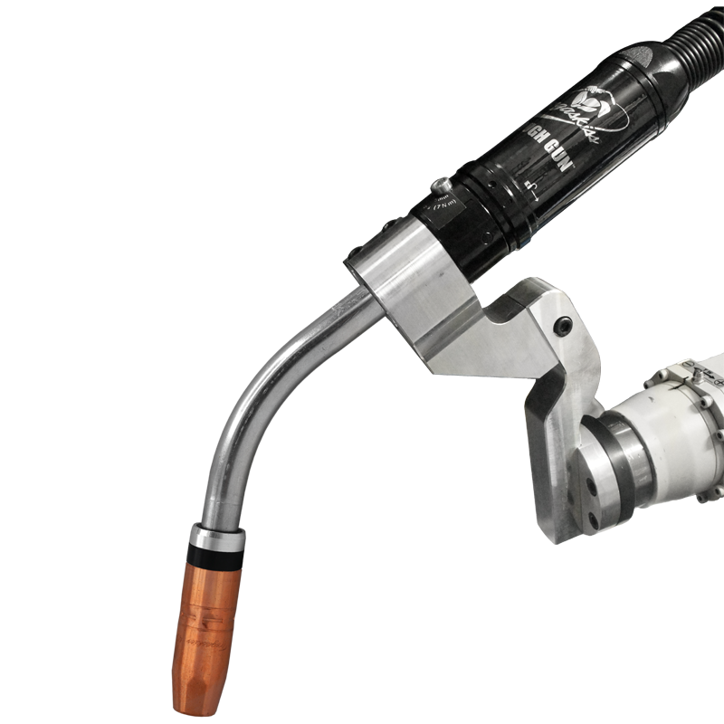
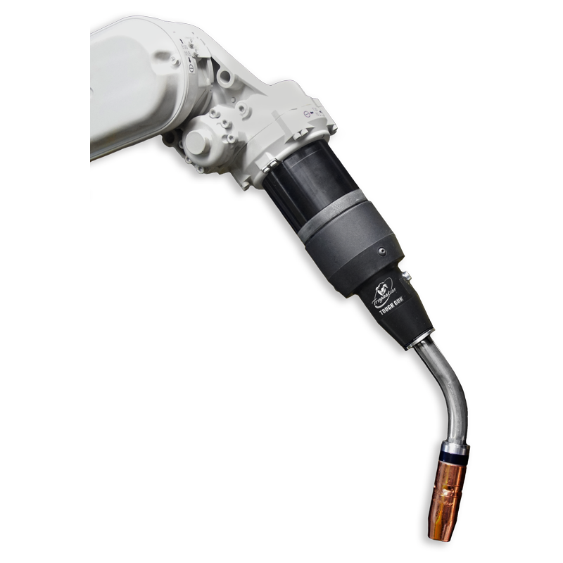
Through-arm robotic welding systems are becoming increasingly common in the industry, as more equipment manufacturers turn to the development of this style compared to conventional robots. However, there are some applications where it is better to use a conventional robotic gun for these systems, instead of the through-arm gun typically chosen. The good news is that most through-arm robotic welding systems allow for mounting either type of gun — providing more options and flexibility depending upon the needs of the application. And while the choice of gun is sometimes an afterthought, it can significantly impact efficiency, throughput and quality of the finished weld. Choosing the best option for the job up front is key. As the name suggests, the power cable assembly of a through-arm MIG gun runs through the arm of the robot as opposed to over the top of it like in a conventional gun. Because of this design, the through-arm gun style is often more durable, since the power cable is protected. However, because conventional guns can be used on either type of system — a through-arm robotic system or a conventional robot — they can sometimes offer greater flexibility, and can be used with more robot makes and models. There are numerous factors to consider when making the choice between a through-arm gun and a conventional robotic gun for a through-arm robotic welding system: Conventional style guns, which typically offer a longer neck, can provide more flexibility in accessing or reaching certain weldments, whereas through-arm guns may have difficulty reaching around fixturing or tooling in some cases. In applications where a through-arm gun is installed and it doesn’t reach the weldment as needed, a conventional gun can be swapped in for access purposes. In addition, conventional guns are often a good choice in smaller, more modular weld cells that feature short-armed robots. Through-arm guns may not work as well in these situations because there is not as much cable, and therefore the robot doesn’t have as much slack for articulation. Also, because of the way the cable lies in a conventional gun, the bend radiuses of the cable are much larger than in through-arm guns. When welding aluminum, for example, wire feeding is a major contributing factor to poor weld quality, and therefore tight bend radiuses are not recommended. This makes conventional guns a good option when robotic welding aluminum. Uptime and throughput are also critical in robotic welding applications, and maintenance is a key factor that impacts productivity, downtime and costs. Conventional guns often provide easier maintenance because everything is outside of the arm, allowing for parts to be changed or repaired quickly to minimize downtime. Another benefit of conventional guns is they tend to be more cost-effective to purchase and can be installed much faster — saving time and money in setup. Through-arm guns provide their own advantages when matched with a through-arm robotic welding system. In applications that require plunging deeply into a fixture or part, a through-arm gun is often a better choice. Think of a through-arm gun as an extension of the robot arm. This extension allows it to access different areas within the part being welded, depending on the application. In addition, because the cables are more protected on a through-arm gun they tend to last longer overall, which helps reduce replacement costs. The through-arm design naturally protects the power cable and makes it less prone to snagging on fixturing, rubbing against the robot or wearing out from routine torsion. With either a conventional gun or a through-arm gun, there are some common best practices that can contribute to success in robotic MIG welding. First, it is critical that the cable is never under tension when using a through-arm gun, to help prevent premature cable failure. Cable tension is visible on a conventional style gun but not on a through-arm gun since the cable runs through the gun. This makes proper setup especially important with through-arm guns. In addition, it’s best to use a cable management system when using a conventional gun to ensure there isn’t too much slack in the cable. With too much slack, the cable will rub on anything around it and possibly catch on fixturing. When a robot moves at production speed, it can break the cable or fixture. Keep these factors in mind, along with joint access requirements and weld cell layout, when making the gun choice to help improve throughput and productivity.
February 13, 2017 Tregaskiss is pleased to announce an improvement to our low-stress robotic (LSR) unicable design whereby the cable conduit will be fixed only on the torch end, and floating on the power pin end. This design change will result in a more flexible, less restricted, longer lasting LSR unicable for all TOUGH GUN® TA3 robotic MIG gun product. Click here for more information about low-stress robotic (LSR) unicables.
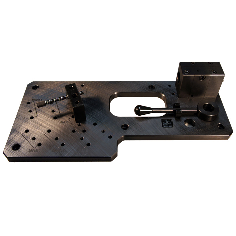
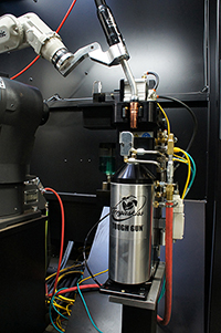
As companies seek to gain a competitive edge, it’s not surprising that some turn to welding automation. It offers numerous advantages, including greater productivity, improved quality and cost savings compared to a semi-automatic welding operation. However, to gain the most out of the investment it’s important to follow some best practices in the weld cell. These considerations include the careful selection, installation and maintenance of gas metal arc welding (GMAW) guns. As with any type of welding equipment, the goal is to implement the GMAW gun in a manner that optimizes performance, reduces downtime and prevents the accrual of unnecessary costs. It is important to note that the considerations for achieving these benefits may vary depending on whether the robotic welding system uses a through-arm gun or a conventional-style gun. Following are some tips to help. All automated welding systems need some form of collision detection to minimize damage to the robot and the GMAW gun in the event of an impact. Today’s robots typically have built-in collision detection software, making it appropriate to use only a solid gun mount to connect and position the GMAW gun. In some cases, companies like the secondary insurance of using a clutch on robots featuring this software. Doing so, however, can add unnecessarily to the expense of the operation, increase weight on the front end of the robot arm and cause the tool center point (TCP) to be less repeatable. When possible, it is preferable to use a solid mount coupled with collision detection built into the robot, instead of a clutch. Solid mounts offer numerous advantages, especially for systems using a through-arm style gun. A solid mount can aid in achieving a more accurate TCP, providing greater repeatability for more consistent welds. They are also more cost effective and lighter weight, which allows for quicker movement and potentially better productivity. The use of a solid mount, in conjunction with a through-arm robotic GMAW gun, typically opens up the work envelope, so the robot arm can better access the weld joint. For systems with a conventional gun, a solid mount provides little benefit over a clutch in terms of opening up the work envelope or increasing productivity due to the position of the gun in comparison to the faceplate of the robot. Air blast is an optional technology on GMAW guns that can help enhance gun performance. This feature can be factory-installed or retrofitted into a gun. Utilizing air blast when possible helps eliminate debris in the front part of the robotic GMAW gun, reducing opportunities for weld contamination that can lead to poor weld quality, costly rework and downtime. As the name implies, the air blast feature blows compressed air through the front of the gun to remove debris. It can be used with air-cooled robotic guns or water-cooled models. In addition to removing debris that can cause poor weld quality or contamination, air blast can help increase the time between cycles by removing spatter from the front of the gun. The air blast function can also be used to cool down the gun between weld passes, to help operations avoid going over the duty cycle limit when using air-cooled guns. Using simulation software to model the proposed weld cycle before selecting and implementing a robotic GMAW gun can help in achieving the best results with an automated welding system. While the goal with an automated welding system is often to move as quickly and freely as possible, it’s important to remember that it’s typically best to limit excessive robot movements, as it results in longer gun life thanks to reduced equipment stress. Simulation programs can be used to determine proper system setup, including TCP requirements and which nozzle and GMAW gun neck are best suited to get the desired joint access or angle. The reach and access of the gun neck, in particular, is an important factor in system movement and stress. Changing the neck angle from 22 degrees to 45 degrees, for example, can have a significant impact on robot articulation. This is where a simulation program is beneficial, since it can be used to determine the type of neck and the neck angle that are best for the application before making the investment. To gain optimum speed and performance from the gun, it may be as simple as slightly adjusting the height of the risers or tooling to gain better access to the weld and reduce stress on the gun. Among several peripherals that can be added to maximize system performance, a neck inspection fixture is one that can help improve throughput, minimize unnecessary downtime — and help gain the best performance from the robotic GMAW gun. A neck inspection fixture verifies that the gun neck is set to the intended TCP and allows the neck to be readjusted after a collision or if it becomes bent during routine welding. When neck adjustment is needed, the welding operator can simply adjust the neck to meet specifications. This helps prevent costly rework due to missed weld joints and can prevent the downtime it takes to reprogram the robot to meet the necessary welding specifications with a bent neck on the gun. In some cases, the welding operator can simply remove the bent neck and exchange it with a spare neck to get the system back online quickly. The damaged neck can be set aside for inspection later, resulting in less interruption to the weld cycle. Using a neck inspection fixture from day one of an automated welding system helps ensure a consistent TCP. Choosing the right gun and cable for the application — and installing them properly — are key steps toward maximizing performance of the robotic GMAW gun. Consider the weld length, the required amperage and the type and thickness of material being welded when selecting a robotic GMAW gun. Air-cooled guns work well on lower amperage applications and high-volume welds. In heavy equipment manufacturing and similar industries, a water-cooled GMAW gun may be necessary to weld on thicker materials for longer periods of time. Water-cooled guns offer high amperages — usually up to 600 amps — at 100 percent duty cycle. Selecting the appropriate neck, power cable and other gun components can also have an impact on productivity and performance. Choosing the proper neck style and length for the application provides the gun with easy and complete access to the weld joint, which helps reduce weld defects and downtime for rework. Available neck angles typically range from 180 to 45 degrees, with varying lengths to accommodate most robotic welding applications. Necks can also be special ordered for custom TCP requirements when necessary. In addition, power cable style and length can also impact efficiency in robotic welding operations. For through-arm applications, the power cable is often sold in set lengths to match a specific model of robot, so the selection process is easier. For conventional style robots, it’s important to verify the exact length needed. Too long of a cable can easily kink or move during the welding process, while too short of a cable can stretch and shorten cable life. In both cases, it can result in downtime, premature cable failure and increased costs. Also, look for a sturdy power cable that can withstand UV damage from the arc and resist wear. Cables with quick-change features can extend cable life, simplify cable changeover and maximize arc-on time when installed properly. Regularly check all connections on the GMAW gun to ensure they are tight and secure. Doing so helps prevent issues that can lead to weld defect and downtime. Tighten front-end consumables and check that all seals are in good condition. Also be certain the power pin is secure. While checking that welding cable leads are secure, look for signs of wear and replace them as necessary. Remove spatter from the GMAW gun nozzle regularly, ideally applying anti-spatter to protect against buildup. Implement a reamer when possible to minimize damage to the gun and front-end consumables. A reamer (or nozzle cleaning station) removes spatter from the nozzle bore and clears away debris that accumulates around the diffuser during welding, resulting in longer life of the consumables and higher weld quality. The reamer can be programmed to run between welding cycles — either during part loading or transfer — so it does not add to the overall cycle time per part. In addition, track the life span of the GMAW gun liner and replace it prior to failure. Replacement liners should be trimmed to the appropriate length using a liner gauge. Automated welding operations that are larger in size may need to do more frequent preventive maintenance. It’s especially important for companies that complete large weldments on thick materials because they stand to have greater costs and downtime for rework in the event of gun failure. Automated welding systems add speed, accuracy and repeatability to the welding operation. They can help companies increase productivity and reduce costs in a relatively short period. Implementing some best practices can help companies extend the life of the GMAW gun and consumables, and optimize performance and efficiency of an automated welding system — offering them the most out of the investment.
Tips to Optimize the Robotic Weld Cell
Tips to Optimize the Robotic Weld Cell

Pre-engineered or custom welding cell?

Choosing the right gun and nozzle

Key considerations for proper layout
The right choices enhance productivity and quality
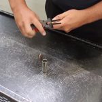
Video | Tregaskiss QUICK LOAD Liner AutoLength System
Tregaskiss® QUICK LOAD® Liner AutoLength™ System
Managing MIG Guns and Consumables for Multiple Applications
Managing MIG Guns and Consumables for Multiple Applications

1. Standardize on a shorter power cable length across weld cells. As a rule of thumb, always use the MIG gun with the shortest power cable possible. A MIG gun with a longer power cable can cause welding operator discomfort since it is heavier, which can cost money and time if he or she has to stop to rest due to fatigue. Additionally, a shorter power cable minimizes the risks of kinks that could cause poor wire feeding and/or an erratic arc, and result in downtime to address birdnesting or rework.

Video | Bernard Centerfire Changing Consumables Challenge
Bernard® Centerfire™ Changing Consumables Challenge
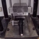
Video | Bernard BTB MIG Gun Handle Impact Test
Bernard® BTB MIG Gun Handle Impact Test
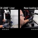
Video | Tregaskiss QUICK LOAD Liner Replacement Race
Tregaskiss® QUICK LOAD® Liner Replacement Race
Graham Corporation Adopts Bernard MIG Guns and Consumables | Customer Testimonial
Graham Corporation Adopts Bernard® MIG Guns and Consumables
Maintaining TCP: How Does Your Robotic MIG Gun Neck Factor In?
Maintaining TCP: How Does Your Robotic MIG Gun Neck Factor In?
The value of TCP
Air-cooled or water-cooled gun?
Getting the best performance
Collision Detection
Neck Inspection Fixture
Spare Necks
Reamer Quality
Optimize the system to ensure proper TCP
What to Know About Liners for Robotic Welding Guns
What to Know About Liners for Robotic Welding Guns

This article has been published as a web-exclusive on thefabricator.com. To read the entire story, please click here.
Bernard and Tregaskiss to Feature Gun Repair/Maintenance Demos at FABTECH 2017
Bernard and Tregaskiss to Feature Gun Repair/Maintenance Demos at FABTECH 2017
Choose the Right Power Cable to Reduce Downtime in Robotic Welding Applications
Choose the Right Power Cable to Reduce Downtime in Robotic Welding Applications
Conventional vs. through-arm guns
Choosing the right cable length
Key best practices

Reduce downtime with the right choice
How Can Customizing a MIG Gun Benefit the Welding Operation
How Can Customizing a MIG Gun Benefit the Welding Operation?

Why Customize?
Starting Out
Consider the welding cell

because the MIG gun selected must meet the amperage and
voltage requirements.Choosing the cable
Neck and handle options

Matching consumables to the gun
Choosing the right MIG gun
DISCONTINUED PRODUCT – Legacy TOUGH GUN ThruArm Product for ABB IRB1600ID
DISCONTINUED PRODUCT –
Legacy TOUGH GUN ThruArm G1 Series Product for ABB IRB1600ID
Tregaskiss Celebrates 50th Anniversary
Tregaskiss Celebrates 50th Anniversary

Signs Your MIG Gun Is Overheating – and How to Prevent It
Signs Your MIG Gun Is Overheating — and How to Prevent It

Watch for the signs
Signs that may indicate the MIG gun is overheating.

Common causes of overheating
Exceeding duty cycle
Not enough stickout

Improper or faulty ground
Preventing gun overheating
PRODUCT IMPROVEMENT – Nozzle Detection Option for TOUGH GUN TT3 and TT3E Reamer
PRODUCT IMPROVEMENT –
Nozzle Detection Option for TOUGH GUN TT3 and TT3E Reamer Robotic Nozzle Cleaning Stations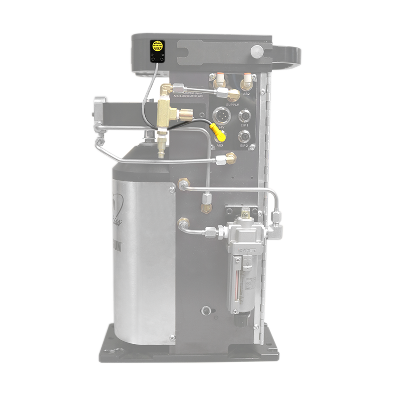
Affected Part Numbers
PRODUCT UPDATE – TOUGH GUN TT3 Reamer Upgrades
PRODUCT UPDATE –
TOUGH GUN TT3 Reamer UpgradesTerminal Strip vs. Wiring Harness


New Easy Access Setup Switches


New Check Valve
PRODUCT IMPROVEMENT – New TOUGH GUN TT3 Reamer Check Valve
PRODUCT IMPROVEMENT –
New TOUGH GUN TT3 Reamer Check Valve
(previously used on the TOUGH GUN TT3 Reamer)
(previously used on the TOUGH GUN TT3E Reamer
(replaces SR-500-20 and OLD TT3E-500-20)Reduce Costly Downtime By Preventing Poor Wire Feeding
Reduce Costly Downtime By Preventing Poor Wire Feeding

Feeder, adapter and other equipment issues
Drive roll considerations

Check the liner

For all consumable systems, inspect the contact tips regularly and replace as necessary.
keep the cable as straight as possible during welding to prevent issues with wire feeding.
If the other components and consumables have been inspected and adjusted as needed and wire feeding remains a problem, it may be that the wrong length of gun is being used. Troubleshooting feeding issues
Related Articles
PRODUCT UPDATE – 300 amp Clean Air Fume Extraction MIG Gun Now Available
PRODUCT UPDATE –
300 amp Clean Air Fume Extraction MIG Gun Now Available
Features and Benefits
Conventional Guns on Through-Arm Robotic Welding Systems: When to Make the Choice
Conventional Guns on Through-Arm Robotic Welding Systems: When to Make the Choice

Considerations in choosing robotic guns
Benefits of conventional guns
When to stay with a through-arm gun
Best practices for performance
PRODUCT IMPROVEMENT – LSR Unicables
PRODUCT IMPROVEMENT –
Low-Stress Robotic (LSR) Unicables
OLD LSR Unicable Design

NEW LSR Unicable Design

Six Tips for Implementing Your Robotic GMAW Gun… and Getting the Most From It
Six Tips for Implementing Your Robotic GMAW Gun … and Getting the Most From It

Tip No. 1: Choose a solid mount instead of a clutch
Tip No. 2: Use an air blast feature
Tip No. 3: Utilize a simulation program
Tip No. 4: Utilize a neck inspection fixture
Tip No. 5: Ensure proper gun and cable installation
Tip No. 6: Conduct proper gun maintenance

gun to ensure they are tight and secure. Doing so
helps prevent issues that can lead to weld defect
and downtime.
Choosing and properly installing the right gun and cable is just the beginning. Proper ongoing maintenance is also an important factor to optimize performance. Optimize the system
![]()