PRODUCT UPDATE –
New Liner Trim Length for Liners 6-Feet Long and Shorter
February 3, 2017
Tregaskiss now recommends trimming all rear-loading conventional and front-loading QUICK LOAD® liners that are 6-feet in length and shorter with a 1/2-inch stick out.
This new trim length provides performance improvements for the liner and cable, and for wire feeding overall. It also helps to reduce some strain on both the liner and the cable while still maintaining a proper liner seat in both the retaining head and the power pin.
Effective late February, all bagged 6-foot Tregaskiss conventional and QUICK LOAD liners will include a new 1/2-inch blue liner gauge along with a technical insert outlining these updated trimming instructions. The outside of each bag will also be marked with a sticker indicating a change to liner trim length.
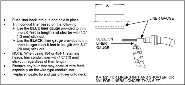
NOTE: Liners longer than 6-foot in length should still continue to be trimmed with a 3/4-inch stick out. No change to liner gauges or trim instructions for conventional or QUICK LOAD liners longer than 6-feet is recommended.
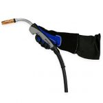
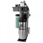
December 16, 2016 Bernard has changed the finish on all Clean Air™ fume extraction gun vacuum tubes and chambers from chrome to black. Effective immediately, all new guns, replacement vacuum tubes and replacement chambers will have the new darker finish. This change is purely aesthetic, and has no impact on performance, part numbering or price. Click here for more information about the Clean Air™ fume extraction gun.
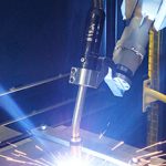
Ensuring a robotic welding cell stays productive and consistently generates a positive return on investment is determined, in large part, by the amount of downtime it incurs. Since robotic welding systems are built for speed, accuracy and repeatability, the cost of arc-off time spent addressing issues is exponentially higher than in a typical welding cell. Having welding operators and robotic weld cell supervisors who can quickly troubleshoot and solve problems makes all the difference when it comes to keeping costs down, generating high-quality results and maintaining optimal efficiency. Here are five common causes of downtime that can occur in a robotic welding operation, along with ways to prevent and address them. If a power cable rubs against the robot, on parts or against tooling, it can prematurely fail and cause unnecessary downtime. In some cases, the cable may even catch on components and wear them out, too. Cables that are too long or too short create excessive strain by either being pulled too tight or flopping around too much and creating strain at the front housing — both of which lead to premature cable failure. These issues are common with conventional style robots, where the power cable connecting to the robotic MIG gun is external to the robot arm. The goal is to set cable length to allow it to exit the front housing with a smooth arc, resulting in minimal strain. Alternately, in the case of a through-arm robotic welding system, downtime often occurs due to improper installation of the gun and/or improper cable length. By adding cable tensioners, which are essentially spring-loaded cable devices that hold the power cable, operators can ensure the cables stay properly supported on a conventional robot. Programming the robot so that it doesn’t accelerate or decelerate too quickly or abruptly can also protect against premature cable failure. In some cases, if the work envelope is quite small, cable rubbing may be unavoidable. Using a protective wrap to shield the cable from rubbing can help. These are available in the marketplace as either a leather or woven nylon cover, or a plastic spiral wrap. When installing a through-arm robotic MIG gun, be sure to position the robot with the wrist and top axis at 180 degrees, parallel to each other. Then install the insulating disc and spacer the same as with a conventional over-the-arm robotic MIG gun. Always be sure the power cable position is correct and has the proper “lie” with the robot’s top axis at 180 degrees, and ensure the power cable has about 1.5 inches of slack when installing it, so it is not too taut. Although consumables may seem like a small part of the robotic welding process, they can have a big impact on how productive and effective an operation is. Nozzles, contact tips, retaining heads (or diffusers) and liners can all fail prematurely or perform poorly for a variety of issues, including spatter or debris buildup, loose connections and improper installation. Issues with the contact tip — especially burnbacks and cross-threading — are also relatively common, and are often caused by a liner being trimmed too short. Choosing durable, easy-to-install consumables is key to minimizing both planned and unplanned downtime in a robotic welding operation. Longer lasting consumables require less frequent changeover. Plus, designs that help less experienced welding operators install consumables correctly result in less troubleshooting. Contact tips with coarse threads and a long tail ensure the tip aligns concentrically in the gas diffuser before the threads engage. These features help minimize the risk of cross-threading. Also, contact tips with greater mass at the front end and that are buried further down in the gas diffuser better withstand heat from the arc to help them last longer. For pulsed welding operations, contact tips with a hardened insert help the tip last 10 times longer than those made of copper or chrome zirconium. That is important since the pulsed waveforms are especially harsh on contact tips and cause them to wear prematurely. Operators should always inspect consumables for signs of spatter or debris buildup during routine breaks in production and, if signs of either are present, replace or clean them. They should also ensure their nozzle cleaning station or reamer is working properly, if one is present, and that it is programmed to ream at a rate that is appropriate for that specific application. It may be necessary to increase the frequency of the anti-spatter spray application or reaming throughout the programmed welding cycle. Check that all consumable connections are clean and secure, as loose connections can generate additional heat through increased electrical resistance, shortening consumable life and/or causing them to perform poorly. Consumable designs that are tapered can also help minimize heat buildup and extend consumable life by offering better electrical conductivity. Welding operators should always follow the manufacturer’s instructions for liner trimming and installation, as a liner can cause inconsistent feeding if cut too short. It is a good idea to use a liner gauge to confirm the correct liner length. There are also spring-loaded modules that work in conjunction with a front-loading liner to help minimize issues if the liner is cut to an incorrect length. These are housed in the power pin and apply forward pressure on the liner after it is installed. They typically allow up to 1 inch of forgiveness if the liner is too short. It is also important to replace liners frequently enough, as a clogged liner full of debris and dirt will not feed properly, and may cause premature contact tip failure. Excessive spatter buildup in consumables can be caused by a nozzle cleaning station that isn’t operating properly and can easily cause unnecessary downtime. Issues related to nozzle cleaning stations can be caused by an incorrect position between this peripheral and the robotic MIG gun nozzle; poor anti-spatter compound coverage; or a dull or improperly sized cutter blade. If a nozzle cleaning station doesn’t appear to be working properly, first check that the robotic MIG gun is concentric to the cutting blade on the reamer. Misalignment of the nozzle can lead to partial cleaning and excessive spatter buildup. Also check that the anti-spatter sprayer, if present, is full, correctly positioned and properly coating the nozzle during spraying. The nozzle should be slightly damp on the inside and outside, and covered up to three-quarters of an inch from the bottom of the nozzle. Note that over-spraying anti-spatter compound can cause nozzles to deteriorate prematurely, so it should never be sprayed for more than half a second. Be sure that the cutter blade matches the diameter of the nozzle bore, so that it can effectively clean during the ream cycle without hitting the nozzle or the gas diffuser. It is also important to have a sharp cutter blade and to make sure that the nozzle is at the correct depth within the jaws of the nozzle cleaning station. Finally, adding an air blast feature to a robotic GMAW gun can help support the nozzle cleaning station’s overall effectiveness. An air blast feature blows high-pressure air through the gun’s front end, which helps remove spatter, debris and other contaminants. This feature can help reduce how often a nozzle cleaning station needs to be used and, ultimately, boost productivity. Collisions can occur as the result of tooling that hasn’t been secured properly, an item inadvertently being left in the weld cell or poor part fit-up. Unfortunately, not only can collisions create unwanted downtime, but they can also damage the robot arm, the robotic MIG gun and/or front-end consumables. Many newer robots are equipped with collision detection software that serves the same function as a shock sensor, but some companies still use a shock sensor as a backup safety measure. For robots that don’t have built-in collision software, a shock sensor can act as a safety device to protect the robot arm and gun from damage if the robot crashes. In the event of a collision, the shock sensor sends a signal back to the robot to alert it to shut down. In order to determine that the shock sensor switch is working properly, operators should conduct a continuity check in the open and closed position of the switch using a multimeter or manually trip it by bumping the neck with their hand. If the sensor is working properly, it will send a signal back to the robot indicating there is a problem. Always reset the shock sensor to its home position and recheck the tool center point (TCP) after a collision, and confirm that both the TCP and clutch are correct. If welding operators are using a newer robot with collision detection software, they should make sure it’s set up correctly and that both the TCP and center of mass or balancing point have been programmed according to the gun manufacturer’s specifications. Doing so helps ensure the robot will react properly in the event of a collision. Poor wire feeding in a robotic welding system is usually caused by one of three things: 1) issues with the liner, such as a clogged liner, 2) a wire feeder that isn’t functioning properly or 3) power cable kinking. Regardless of the cause, the result is poor arc stability and weld quality. As previously mentioned, regularly changing the liner and using a robotic MIG gun with an “air blast” feature help eliminate debris in a liner. If an air blast feature is not available, welding operators can also manually blow compressed air through the liner periodically. If it is suspected that the wire feeder’s drive rolls are the culprits of the poor wire feeding, there are two ways to further investigate and assess the situation. One is to visually inspect the drive rolls for signs of wear, and the other is to conduct a “two-finger” test. The latter involves disengaging the drive rolls, grasping the welding wire and pulling it through the gun. The wire should be able to be pulled easily with two fingers. Lastly, look for kinks in the power cable, which can also lead to poor wire feeding, and then straighten or unwind the cable, if necessary. Remember, knowing how to troubleshoot common problems in a robotic welding operation can make the difference between costly downtime and consistently productive, arc-on time. And making the effort to address potential issues up front can actually save time and money in the long run.
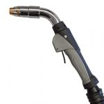
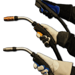
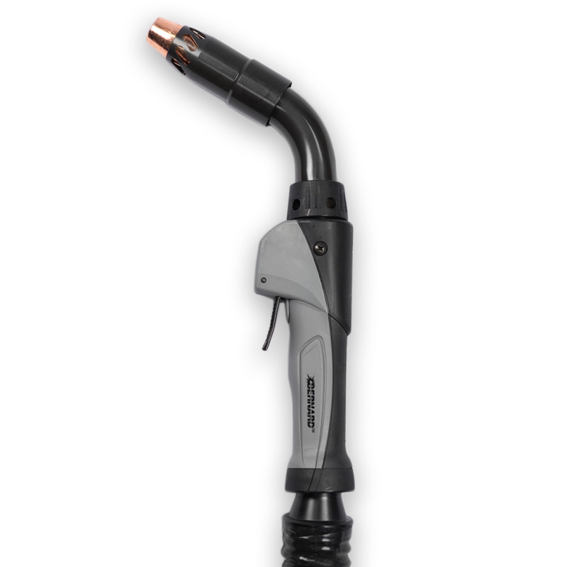
BEECHER, Ill., November 22, 2016 – Bernard has announced the expansion of handle options from six to seven choices for its BTB semi-automatic MIG gun line. Handle options now include the new C series straight handle, which provides all the benefits of the existing T series straight handle, plus additional ergonomic benefits such as a handle overmold and rear swivel — at no extra cost. Designed for maximum configuration flexibility and industrial-grade performance, Bernard BTB semi-automatic MIG guns provide users with options ranging from 200 to 600 amps with numerous cable length choices between 8 to 25 feet. The new C series straight handle is available for guns rated from 200 to 500 amps. By visiting the BTB MIG gun configurator, users can customize their gun with the C series straight handle or other handle options, choosing from three high performance consumables series — Centerfire™, TOUGH LOCK® or Quik Tip™ consumables — and multiple trigger options. Insight Limited™ triggers are an available option when selecting the new C series handle, and are designed specifically for use with power sources from Miller Electric Mfg. Co. that feature Insight Centerpoint™ welding information management systems. Users can also choose from 20 fixed and rotatable necks in various angles and lengths on any front handle style, and power cables are available in industrial-grade or steel monocoil to meet a variety of user needs. The BTB semi-automatic MIG guns feature a one-year warranty plus lifetime warranties on both the rear strain relief and the front handle. Additionally, BTB guns equipped with the new C series straight handle or a T series straight handle feature the double-life MIG gun system. When the front end of the gun becomes worn from routine use, this system allows users to simply flip the front end of the gun with back end for additional use.
December 18, 2019 Tregaskiss manufactures TOUGH GUN® TA3 through-arm welding torches for many Yaskawa® Motoman® robot models including but not limited to: On the current robot models listed above, the spacers and through-arm cables on a Tregaskiss® gun may originate from either Tregaskiss or from Yaskawa Motoman. It is important to note that the spacers and cables from Tregaskiss have significantly different dimensions than these same items from Yaskawa Motoman. This means that they are NOT interchangeable. Ordering the wrong replacement spacer and/or cable for an existing installation will significantly impact Tool Center Point (TCP) and cable life – please see Configuration Comparison Chart below for both solid mount and clutch mount setups with a short 45-degree neck for reference. For each model above, when a TOUGH GUN TA3 MIG gun is configured through Tregaskiss, the complete torch solution is Tregaskiss branded and includes: consumables, neck, torch, cable and power pin. For AR/MA1440, MH12, AR/MA2010, AR/MA3120, AR1730, MH24 models, the system also includes a Tregaskiss-specific aluminum spacer which allows us to bury the cable termination into the torch and away from the articulation on axis 5. When Yaskawa Motoman integrates a welding solution with Tregaskiss product, a Motoman through-arm cable replaces the Tregaskiss through-arm cable for all models listed above (consumables, neck, torch and power pin remain Tregaskiss branded). For AR/MA1440, MH12, AR/MA2010, AR/MA3120, AR1730, MH24 models, the system also includes a Motoman-specific plastic torch spacer which allows us to bury the cable termination into the torch and away from the articulation on axis 5. This Motoman spacer is shorter than the Tregaskiss spacer and as a result, the Motoman cable for this setup is also shorter than the Tregaskiss-specific setup. NOTE: Reference chart above is applicable for Yaskawa Motoman robot models AR/MA1440, MH12, AR/MA2010, AR/MA3120, AR1730, MH24. 58SM016 Solid Mount Solid Mount Motoman Solid Mount 58SM002 58SM038 58SM038AW MA3120, AR3120 Solid Mount AS-114-13 58SM032 58SM032A 58SM032W 58SM032AW 58SM039 58SM039W Clutch 58CM016A 58CM016AW Motoman EA1900 XRC Clutch N/A 58CM001A Motoman 58CM035 Motoman 58CM002AW AS-114-13 Clutch 58CM031W 58CM031AW Clutch 58CM032 58CM032A 58CM032W 58CM039W NOTE: If Tregaskiss® TOUGH GUN I.C.E.® technology is required for your application, the cable must be purchased from Yaskawa Motoman for all of their robot models. If you require Yaskawa Motoman components, please contact Yaskawa Motoman directly. Otherwise, if you require Tregaskiss components, please contact us for assistance.
The new C series straight handle expands our handle offering from six to seven options within our Bernard BTB MIG gun configurator. This new handle provides all the same benefits as our current T series straight handle, plus additional enhancements such as comfortable handle overmolding and an ergonomic rear swivel. Click here to learn more about the new C series straight handle.
Being as comfortable as possible contributes to welding operator safety and productivity — and it’s a factor that can impact the quality of the finished weld. There are numerous issues that play a role in welding operator comfort, including the heat generated by the welding process, the repetitive motions and, at times, cumbersome equipment. These challenges can take a toll, resulting in aches, fatigue and physical and mental stress for welding operators. There are some steps, however, to help reduce the impact of these factors. These include choosing the right equipment for the job, utilizing tools and accessories designed to improve operator comfort, and following some best practices that promote proper operator form. Promoting operator comfort can lessen the chance of injuries associated with repetitive movement, as well as reduce overall fatigue. Choosing a GMAW gun that meets the needs of the application — and in some cases customizing the gun — is a critical way to impact welding operator comfort so he or she can achieve the best results. A gun’s trigger, handle, neck and power cable design all help determine how long a welding operator can comfortably weld without experiencing fatigue or stress. The application’s weld joint geometry also plays a role in welding operator comfort, and it impacts what components to choose for optimal joint access. Here are some issues to consider in GMAW gun selection that can impact comfort, as well as quality and productivity: Gun amperage can have a significant impact on welding operator comfort because, typically, the higher the amperage, the larger — and heavier — the gun. Therefore, a larger amperage gun may not be the best choice if that amperage rating is not necessary to meet the needs of the application. Choosing a smaller amperage gun when possible can help minimize fatigue and stress on the welding operator’s wrists and hands. In selecting the right amperage, consider the application’s duty cycle requirements. Duty cycle refers to the number of minutes in a 10-minute period that a gun can be operated at its full capacity without overheating. For example, a 60 percent duty cycle means six minutes of arc-on time in a 10-minute span. Most applications do not require the welding operator to use the gun constantly at full duty cycle. In many cases, a higher amperage gun is only needed when the power source is being run continuously. Handle options for GMAW guns include straight and curved styles. The right choice typically comes down to the specific process, application requirements and — most often — operator preference. Keep in mind that a smaller handle tends to be easier to hold and maneuver. In addition, the option of a vented handle promotes improved operator comfort, since this style can cool down faster when the gun isn’t in use. While operator comfort and preference are important considerations, handles must also meet the gun and application’s amperage and duty cycle requirements. A straight handle provides flexibility by allowing to mount the trigger on the top or bottom of the handle. Putting it on top is a good choice to improve operator comfort in high-heat applications or for those that require long welds. There are numerous trigger choices that can improve comfort and safety. Look for a trigger that doesn’t require more pull force than necessary to maintain the arc, to minimize stress on the operator. Also, locking triggers are a good option to alleviate stress on the welding operator’s finger caused by grasping, sometimes called “trigger finger.” A locking trigger, as its name implies, can be locked into place. This feature allows the welding operator to create long, continuous welds without having to hold the trigger the entire time. Locking triggers also help distance the welding operator from the heat generated during welding, making them well-suited for high amperage applications. Another part of the gun that plays a role in operator comfort is the neck. Rotatable and flexible necks are available in various lengths and angles, and can be adjusted to meet specific application needs, offering many choices to help reduce operator strain. Joint access, gun amperage and duty cycle required for an application are important considerations when choosing a gun neck. For example, a longer gun neck can improve operator comfort when the application requires a long reach. A flexible neck can do the same when accessing joints in a tight corner. The best choice for pipe welding might be an 80-degree neck, while a 45- or 60-degree neck might be better suited for welding in the flat position. Rotatable necks allow welding operators to rotate the neck as needed, such as in out-of-position or overhead welding. In cases where you need a longer neck, another option is to utilize a neck coupler, which is a tool that combines two gun necks. The flexibility provided by these numerous neck options can result in reduced opportunity for operator fatigue, strain and injury. The power cable adds weight to the gun and can also add clutter to the workspace. Therefore, smaller and shorter cables are recommended, as long as they meet the needs of the application. Not only are shorter and smaller cables typically lighter and more flexible — to ease the fatigue and strain on a welding operator’s hands and wrists — but they also help reduce clutter and tripping hazards in the work area. Different welding guns can offer different “balance,” which refers to the feel and ease of movement experienced when the welding operator holds the gun. For example, a heavier gun that is balanced properly can lessen operator fatigue compared to a heavier gun that is not balanced properly. A gun that is properly balanced will feel natural in the operator’s hands and be easy to maneuver. When a gun is not balanced correctly, it might feel more unwieldy or uncomfortable to use. This can make a difference in operator comfort and productivity. Because welding applications differ for every welding operator, customizable GMAW guns can be a good option to gain greater comfort. Poor welding operator comfort can directly impact productivity and efficiency. Some gun manufacturers offer online resources to help welding operators configure a GMAW gun for the exact specifications of the job. This helps ensure the gun is suited to operator preferences and the needs of the application — for greater comfort and productivity. ttFor example, most welding operators do not make huge, sweeping movements when using a GMAW gun. Instead, they tend to use more minute, delicate maneuvering of the gun. Some configurations allow users to choose an option available for fume extraction guns — for example, a ball and socket swivel design that helps the vacuum hose to move separately from the handle. This improves flexibility and reduces the wrist fatigue for the welding operator. Utilizing proper weld position and form are additional ways that welding operators can maximize comfort on the job. Repetitive strain or prolonged uncomfortable postures can result in operator injury — or even the need for costly and time-consuming rework due to poor quality welds. Whenever possible, place the workpiece flat and move it into the most comfortable position. It’s also important to maintain a clean working environment. In some cases, a fume extraction gun paired with the proper portable fume extraction system can be a viable option to replace wearing a powered air purifying respirator and lessen the amount of equipment the welding operator must wear. To maintain compliance and safety, it’s always a good idea to consult an industrial hygienist to be certain that’s an appropriate step. In addition, operator comfort can be maximized by using stable posture and avoiding awkward body positioning, and by not working in one position for long periods. When welding in a seated position, operators should also have the workpiece slightly below elbow level. When the application requires standing for long periods, use a foot-rest. Having the right equipment, choosing equipment or accessories that are easy to operate and promote operator comfort, and utilizing proper welding technique and form are all important steps toward achieving a comfortable, safe work environment for welding operators. Lightweight welding guns with appropriate handle and neck designs for the job and for the operator can help achieve safe and productive results. The reduction of heat stress, wrist and neck fatigue and repetitive motions can also help decrease overall physical and mental stress for welding operators. To achieve optimal results, consider the numerous options available in tailoring a GMAW gun that is right for the application and operator preference.
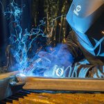
Self-shielded flux-cored arc welding (FCAW-S) offers numerous benefits, including good weldability, high deposition rates, and excellent chemical and mechanical properties. These make the process a common choice for many applications, such as structural steel erection, bridge construction and heavy equipment repair. But like any welding process, it is not without its challenges. There are a few simple tips and best practices that can help address these challenges. Using this knowledge — with a bit of practice — can save time, money and frustration, and help achieve high weld quality. Slag inclusions — the result of molten flux from inside the welding wire becoming trapped inside the weld — can commonly occur in out-of-position and multi-pass FCAW-S applications. Preventing this issue depends on following key best practices and utilizing proper welding techniques. These include: Porosity is a common weld defect that occurs when gas is trapped in the weld. Cleaning the base material thoroughly prior to welding is the main way to prevent this problem. Remove all dirt, rust, grease, oil, paint, moisture and other contaminants from the full length of the weld joint. While welding, be sure to maintain wire stick-out of no more than 1 1/4 inch beyond the contact tip. In addition, using filler metals containing added deoxidizers can help prevent porosity and allow for welding through light contaminants. However, these wires are not a replacement for proper cleaning. Another defect, wormtracking, refers to marks on the surface of the weld bead caused by gas that the flux inside the wire creates. Take care to avoid excessive voltage for the wire feed setting to help prevent this problem. In situations where wormtracking occurs, reduce the voltage in increments of 1/2 volt until the problem stops. Undercutting and lack of fusion Lack of fusion occurs when the weld metal does not properly fuse with the base material or with the preceding weld bead during multi-pass welding. Using an improper gun angle is the main cause of this problem. Maintain heat input and correct work angle of the gun to help prevent lack of fusion. Use a gun angle drag of 15 to 45 degrees, and keep the arc on the trailing edge of the welding puddle. When using a weaving technique, hold the arc on the groove’s sidewall. A dirty work surface is another common cause of lack of fusion. Proper and thorough cleaning of the surface before welding and in between passes is recommended. Undercutting causes a weaker area at the toe of the weld by allowing a groove to melt in the base metal that is not filled in by the weld metal. This defect can often lead to cracking. To prevent undercutting, follow welding parameters for the appropriate welding current and voltage. Gun angle also plays a key role in this issue. In addition, be sure to maintain a travel speed that allows the weld metal to fill the melted-out areas of the base material completely. When it comes to weld joint penetration, too much and too little are both problematic. Good joint penetration is critical to completing high-quality welds, so it’s important to pay attention to how much weld metal is going into the joint. When weld metal melts through the base metal and hangs underneath the weld, this is excessive penetration. It is most often caused by too much heat. Avoid this problem by maintaining proper heat input for the application. Lower the voltage range, reduce wire feed speed and increase travel speed. When the problem is a lack of penetration — or a shallow fusion between the weld and base metals — taking the opposite steps will help: increase the voltage range and wire feed speed, while reducing travel speed. Joint preparation also plays a role in proper penetration. To maintain the right wire extension and obtain necessary arc characteristics for good weld quality, it is imperative to access the bottom of the groove. As with any welding process, FCAW-S can present some challenges. By utilizing proper welding technique and taking steps to address the issues, it will be easier to identify and solve problems quickly — or even prevent them from occurring — in order to reap the productivity and quality benefits the process offers.
WINDSOR, Ontario. Sept. 13, 2016 — A new online configurator from Tregaskiss makes it quick and easy to customize the company’s TOUGH GUN® TT3 reamer robotic nozzle cleaning stations to match the needs of their welding application. Users simply follow a series of steps to configure a reamer model, first selecting the V-block and cutter blade to match the outside diameter (OD) and bore of their robotic MIG gun nozzle. Users can then select from various add-ons, including a wire cutter, lubricator, air blast and/or filter/regulator. Tregaskiss also offers the option to choose accessories sold separately, such as a reamer stand, anti-spatter liquid and an anti-spatter multi-feed system. After choosing all desired components, the configurator provides a summary of the selections, along with a part number for the reamer. Users are given the option to request a quote for the reamer, download spec sheets or owner’s manuals, print the selection summary and part number, or contact Tregaskiss for more information. To help users save time, the online configurator incorporates a new reverse part number lookup function that provides a complete replacement parts list for their reamer based on an existing part number. The reamer is available for customization in both analog and Ethernet models. The analog TOUGH GUN TT3 reamer features improvements to the sprayer system, new plug and play replacement parts, and simplified internal wiring for reliable performance and ease of maintenance. The TOUGH GUN TT3E reamer offers the same high levels of durability, serviceability and repeatability and is enhanced with digital Ethernet communications for better integration into facilities’ digital controls infrastructure.
When it comes to welding, too much of a good thing can often add up to unnecessary costs, potential downtime and lost productivity — especially if you have too large of a MIG gun for your application. Unfortunately, many people believe a common misconception: that you need a MIG gun rated to the highest amperage you expect to weld (e.g., a 400-amp gun for a 400-amp application). That is simply not true. In fact, a MIG gun that provides a higher amperage capacity than you need typically weighs more and may be less flexible, making it less comfortable to maneuver around weld joints. Higher amperage MIG guns also cost more. The truth is, because you spend time moving parts, tacking them and performing other pre- and post-weld activities, you rarely weld continuously enough to reach the maximum duty cycle for that MIG gun. Instead, it’s often better to choose the lightest, most flexible gun that meets your needs. For example, a MIG gun rated at 300 amps can typically weld at 400 amps and higher — for a limited amount of time — and do just as good of a job. In the United States, the National Electrical Manufacturers Association, or NEMA, establishes the MIG gun rating criteria. In Europe, similar standards are the responsibility of Conformité Européenne or European Conformity, also called CE. Under both agencies, MIG guns receive a rating that reflects the temperatures above which the handle or cable becomes uncomfortably warm. These ratings, however, do not identify the point at which the MIG gun risks damage or failure. Much of the difference lies in the duty cycle of the gun. Manufacturers have the option of rating their guns at 100-, 60- or 35-percent duty cycles. For that reason, there can be significant differences when comparing different MIG gun manufacturer’s products. Duty cycle is the amount of arc-on time within a 10-minute period. One MIG gun manufacturer may produce a 400-amp MIG gun that is capable of welding at 100 percent duty cycle, while another manufactures the same amperage MIG gun that can weld at only 60 percent duty cycle. In this example, the first MIG gun would be able to weld consistently at full amperage for a 10-minute time frame, whereas the latter would only be able to weld for 6 minutes. Before deciding which MIG gun to purchase, it is important to review the duty cycle ratios for the product. You can typically find this information in the product literature or on the manufacturer’s website. Based on the gun rating explanation above, it is also essential for you to consider the length of time you spend welding before you make your MIG gun selection. Look at how much time you actually spend welding over the course of 10 minutes. You may be surprised to discover that the average arc-on time is usually less than 5 minutes. Keep in mind that welding with a MIG gun rated to 300 amps would exceed its rated capacity if you were to use it at 400 amps and 100-percent duty cycle. However, if you used that same gun to weld at 400 amps and 50-percent duty cycle, it should work just fine. Similarly, if you had an application that required welding very thick metal at high current loads (even 500 amps or more) for a very short period of time, you might be able to use a gun rated at only 300 amps. As a general rule, a MIG gun becomes uncomfortably hot when it exceeds its full duty cycle temperature rating. If you find yourself welding for longer on a regular basis, you should consider either welding at a lower duty cycle or switching to a higher rated gun. Exceeding a MIG gun’s rated temperature capacity can lead to weakened connections and power cables, and shorten its working life. There are two types of heat that affect the handle and cable temperature on a MIG gun and also the amount of time you can weld with it: radiant heat from the arc and resistive heat from the cable. Both of these types of heat also factor into what rating of MIG gun you should select. Radiant heat is heat that reflects back to the handle from the welding arc and the base metal. It is responsible for most of the heat encountered by the MIG gun handle. Several factors affect it, including the material being welded. If you weld aluminum or stainless steel, for example, you will find that it reflects more heat than mild steel. The shielding gas mixture you use, as well as the welding transfer process, can also affect radiant heat. For example, argon creates a hotter arc than pure CO2, causing a MIG gun using an argon shielding gas mixture to reach its rated temperature at a lower amperage than when welding with pure CO2. If you use a spray transfer process, you may also find that your welding application generates more heat. This process requires an 85 percent or richer argon shielding gas mixture, along with a longer wire stick out and arc length, both of which increase the voltage in the application and the overall temperature. The result is, again, more radiant heat. Using a longer MIG gun neck can help minimize the impact of radiant heat on the handle by placing it further from the arc and keeping it cooler. The consumables you use can in turn affect the amount of heat that the neck absorbs. Take care to find consumables that connect tightly and have good mass, as these absorb heat better and can help prevent the neck from carrying as much heat to the handle. In addition to radiant heat, you may encounter resistive heat in your welding application. Resistive heat occurs by way of electrical resistance within the welding cable and is responsible for most of the heat in the cable. It occurs when the electricity generated by the power source cannot flow through the cable and cable connections. The energy of the “backed up” electricity is lost as heat. Having an adequately sized cable can minimize resistive heat; however, it cannot eliminate it entirely. A cable large enough to completely eliminate resistance would be too heavy and unwieldy to maneuver. Using a lighter MIG gun can often improve productivity since it is easier to maneuver for longer periods of time. Smaller MIG guns can also reduce your susceptibility to repetitive motion injuries, such as carpal tunnel syndrome. When choosing your MIG gun, remember that not all products are created equal. Two MIG guns rated to 300 amps could vary widely in terms of their overall size and weight. Take the time to research your options. Also, look for features like a ventilated handle that permits air to flow through it and keeps it running cooler. Such features can often allow a gun to be rated to a higher capacity without adding any size or weight. Finally, assess the time you spend welding, the process and shielding gas you use, and the materials you are welding. Doing so can help you select a gun that strikes the ideal balance between comfort and capacity.
Investing in a robotic welding system goes beyond the initial purchase — it is equally important to find ways to maximize the abilities of this equipment. When implemented properly, speed, accuracy and cost savings are fundamental benefits of welding automation. These factors rely on everything from the robot itself to personnel overseeing the weld cell to the smallest factors, like the front-end consumables on the robotic MIG gun. Although consumables may seem insignificant, the nozzles, contact tips and gas diffusers can have a huge impact on performance. The right combination reduces downtime and waste, and improves productivity and quality. In fact, a contact tip often serves as a barometer of the overall effectiveness of the welding process, by indicating how optimized it is — or isn’t. Always consider consumables as a part of the planning process when working with an integrator to design a robotic welding system. Doing so prevents issues with joint access — if the consumables are an afterthought, it’s possible that the front-end of the robotic MIG gun won’t be able to maneuver properly around the part or the fixturing to reach the joint. Reconfiguring the system can be time-consuming and costly. Bottleneck, straight or tapered nozzles can help accommodate for joint restrictions since they are narrower than standard nozzles and provide better access. Take caution when using tapered nozzles, however, as they are thinner and may not be able to withstand the higher amperage or higher-duty-cycles of robotic welding, leading to more frequent changeover. They may also collect more spatter buildup due to their narrower bore. For jobs requiring 300 amps or greater and/or those with a high level of arc-on time, a heavy-duty style nozzle with thicker walls and insulators will be more heat-resistant. It’s usually best to select the heaviest duty consumable for the application that still allows access to the tooling. Consult a robotic integrator or welding distributor whenever in doubt. Consumables come in a variety of materials and sizes. For example, heavy-duty contact tips are available in copper or chrome zirconium and feature an outside diameter (OD) of around 0.3125 inch. In addition to pulsed welding (discussed more later), higher-amperage applications can benefit from chrome zirconium contact tips, as they generally offer a longer performance life than copper contact tips. Nozzles are typically available in brass or copper. The brass variety tends to be more spatter-resistant. However, these nozzles have a lower melting point and can fracture or deteriorate more quickly than copper, if they come into direct contact with the molten weld pool. This factor makes them ill-suited for tight access applications. Extra-heavy-duty consumables are also available in the marketplace and are good for high-amperage applications requiring larger-diameter welding wires — 0.052 inch and greater. Contact tips in this category generally have an outer diameter of about 0.375 in. Regardless of the material, look for consumables that are well-machined with a smooth, consistent surface. These are less prone to spatter buildup and may therefore last longer. In some cases, these consumables may be more expensive, but it’s important to weigh the upfront costs with the longer-term savings of minimizing changeovers and downtime. Likewise, poorly functioning consumables, or ones that are simply not appropriate for the application, can generate weld quality issues that compound productivity delays and could lead to expensive rework. Robotic welding systems typically operate for longer periods of time at higher amperages than semi-automatic applications. As mentioned, heavy-duty consumables, which are more heat-resistant than standard-duty consumables, are often used. But they aren’t always necessary. In some cases, standard-duty consumables can replace them. For example, in applications with low duty cycles, there is less heat because less time is spent welding, and standard-duty consumable will suffice. It is important, however, to test for durability on a given application before introducing them into the welding operation. Also, when frequent consumable changeover is part of a company’s protocol, standard-duty consumables could work on high-amperage applications because the welding operator changes them over before a failure occurs from high heat levels. Mechanical wear on the contact tip is inevitable in any welding application, as the constant friction of the welding wire feeding through the tip naturally wears on it. But electrical wear also can be an issue in high-amperage welding that uses a pulsed welding mode. Pulsed welding programs have a unique waveform that causes the power source to move between low background currents and high peaks, which is particularly harsh on consumables. Often these waveforms reduce weld spatter but are harder, electrically speaking, on the contact tip. It is important to select contact tips that are durable enough for the application, and often chrome zirconium contact tips are the best choice for this welding mode. It is also a good idea to monitor contact tip usage regularly in pulsed welding applications. Changing over contact tips before they are too damaged can help to prevent issues such as loss of electrical conductivity, burnbacks and excessive spatter, resulting in poor weld quality, rework and downtime. Welding operators can use the time during routine breaks in production to changeover contact tips and maximize efficiencies. Robotic welding often uses large drums of wires — 500 to 1,000 pounds — to minimize changeover. The wire in these drums tends to have less cast or helix than wire that feeds off of a smaller spool and, as a result, feeds through the contact tip in a relatively straight fashion, making little or no contact with the tip. This action minimizes the electrical conductivity necessary to create a good arc and a sound weld. It also can cause the welding wire to contact the part being welded and arc back into the contact tip, creating a burnback. This condition automatically creates downtime because the contact tip needs to be changed. Undersizing contact tips, particularly when using solid wire in a high-amperage application, is a good fix. For example, a 0.040-in.-diameter contact tip could work for a 0.045-in. wire. The welding operator should check with a trusted welding distributor for applications requiring metal-cored wires because undersizing is not always an option. It’s worth considering the impact that the wire type has on the longevity of the contact tips as well. Non-copper-coated solid wires, for example, tend to wear contact tips more quickly than copper-coated ones because the coating acts like a lubricant to improve feedability. Improved feedability can, in turn, lead to longer contact tip life. A nozzle cleaning station or reamer cleans spatter from the robotic gun nozzle and clears away debris in the gas diffuser that accumulates during the welding process. Reamers can be outfitted with a sprayer that applies a water-based anti-spatter compound to protect the nozzle, retaining head and workpiece from spatter. Reamers and anti-spatter combined are a good defense against premature consumable failure and poor shielding gas coverage (caused by spatter-blocked gas ports), and can help extend the life of front-end consumables. For the best results, place the nozzle cleaning station close to the robot so it’s easily accessible, and program the robot to use it in between cycles — during part loading or tool transfer, for example. It should only take six seconds for the nozzle cleaning station to complete its job and the results are measurable: less spatter and longer consumable life.
BEECHER, Ill./WINDSOR, Ontario. August 9, 2016 – Bernard and Tregaskiss have introduced a new reverse part number lookup function for their semi-automatic and robotic MIG gun online configurators — online tools that allow users to customize a MIG gun for their exact needs, by selecting amperage, neck style and angle, consumables and more. The new time-saving reverse part number lookup function provides users with the complete replacement parts list — from power pin to contact tip — for previously configured MIG guns, based on the existing part number. Reverse lookup information is available for the Bernard® BTB semi-automatic MIG guns and Clean Air fume extraction guns, along with Tregaskiss® TOUGH GUN® CA3 and TA3 robotic MIG guns. It is also available for the TOUGH GUN G2 series robotic MIG guns (both conventional and througharm styles) and features additional functionality for these products to simplify conversion to a TOUGH GUN CA3 or TA3 robotic MIG gun. Users of Tregaskiss robotic water-cooled MIG guns (600 amp) and TOUGH GUN TT3 reamers can also benefit from this reverse part number lookup function. To utilize the part number lookup function, users can visit Tregaskiss.com/ConfigureMyGun and follow the prompts on the home screens to enter an existing part number.
When it comes to robotic welding operations, uptime is key. Minimizing air movements and ensuring consistent workflow are just as important as selecting the right robot, power source and robotic gas metal arc welding (GMAW) gun. Everything should work in conjunction to bring about the greatest efficiencies. The result can be higher productivity, better weld quality and an improved bottom line — not to mention, the potential for a competitive edge. A nozzle cleaning station (also called a reamer), along with a sprayer for delivering anti-spatter compound, can be simple and effective additions to the robotic weld cell — and ones that offer a good return on investment. Anti-spatter compound can also be delivered from a single large drum via a multi-feed system to numerous robotic weld cells. Anti-spatter compound protects the front-end consumables on a robotic GMAW gun from excessive spatter accumulation, which can restrict shielding gas flow, increasing the risk for porosity. This compound also helps prolong the life of the nozzle, contact tips and gas diffuser, and can reduce downtime for consumable changeover. In addition, it can lower the cost for consumable inventory (and its management), and reduce operating costs by improving weld quality and lessening rework by way of consumables that operate at peak performance. All of these factors contribute to a more productive and profitable welding operation. The what, when and where of anti-spatter compounds Constant-voltage (CV) applications and those utilizing solid wire and/or the welding of galvanized steel tend to produce high levels of spatter, and therefore, often benefit the most from the use of anti-spatter compound. However, the application of anti-spatter compound is ideal for any high-volume, high-production environment seeking to minimize potential weld quality issues, extend consumable life and also reduce downtime. Its application can easily be programmed so that it is sprayed onto the consumables after each ream cycle, during routine pauses in production for part changeover. When selecting an anti-spatter compound, be certain that it is capable of providing uniform coverage to protect the entire nozzle, that it cleans up easily and leaves no residue, and that it is compatible with the nozzle cleaning station being used. Water-soluble anti-spatter compound is the most popular option, and is typically non-toxic and eco-friendly. Oil-based anti-spatter compound is also available in the marketplace, but is generally less desirable to use because it is more difficult to clean up if it settles on fixtures or elsewhere in the weld cell. It is also important to note that oil-based anti-spatter compound is not always compatible with all nozzle cleaning stations and it can clog up this equipment. Despite the fact that the more popular water-based anti-spatter compound is non-toxic, welding operators and/or maintenance personnel should still take care when handling and using it. They should avoid breathing in spray mists and always wash their hands after coming in contact with the compound (for example, when filling the sprayer). The use of a NIOSH certified (or equivalent) respirator during spraying is recommended. Also, personnel should wear Nitrile or Butyle gloves and wear chemical safety goggles for the best protection. Local exhaust ventilation near the sprayer is also important. Store anti-spatter compound containers according at the temperatures recommended by the manufacturer. Best practices for anti-spatter compound use Spraying for about a half-second is the standard recommendation. If a company finds that it is necessary to spray the anti-spatter compound any longer, that usually means the sprayer is too far away. In fact, anti-spatter compound should never be sprayed for three or more seconds. In addition to causing harm to the consumables, excess spraying can leave a residue of the compound in the weld cell that could lead to safety issues, such as slick floors and slipping hazards. Over-application of anti-spatter compound may also damage equipment, such as power sources, by adversely affecting electrical circuits it comes in contact with. Some manufacturers offer a spray containment unit, which can help capture excess anti-spatter compound. This 3 to 4-inch unit fits over the spray head on the anti-spatter compound sprayer. After the spatter has been cleared from the nozzle during the reaming cycle, the nozzle docks on the spray containment unit. An opening at the top of the cylinder allows the anti-spatter to spray onto the nozzle while an O-ring seals the nozzle in place so only the outside edge and inside of the nozzle are sprayed. The spray containment unit also collects any anti-spatter compound runoff at the bottom of the unit so it can be easily drained into a container and disposed of properly. Anti-spatter compound cannot be reused and should be disposed of in accordance with federal, state and local environmental control regulations. When employing a spray containment unit, it is important to inspect it regularly, removing any spatter or debris from the bottom that could prevent it from working properly. As part of a preventive maintenance activities, clear the screen or filter inside the unit of contaminants using clean, compressed air. Doing so helps ensure that the screen can continue to fulfill its intended purpose of improving air quality. As with any part of the robotic welding operation, when employed properly, this unit and the use of anti-spatter compound can yield positive results. Always follow the manufacturer’s recommendation for use and consult with a trusted welding distributor with any questions. In conjunction with anti-spatter compound, a nozzle cleaning station improves quality and productivity in robotic weld cells by helping extend consumable life and reducing downtime for changeover. Here are some tips to get the most out from this equipment. Correct placement: Place the nozzle cleaning station in close proximity to the robot so it is easily accessible. Match parts and sizes: Make sure the V-block inside the top of the nozzle cleaning station is the correct size for the nozzle, that the cutter blade is the correct size for the nozzle bore, and that the insertion depth of the nozzle to the reamer is adequate. Monitor the home signal: Monitor the home signal on the nozzle cleaning station to reduce issues during the cleaning cycle and minimize guesswork regarding whether the equipment is ready for use or done with its cycle. Clean and scrape parts: Clean the top seal on the spindle under the cutter and make sure all clamp faces are kept clean by scraping the faces and jaws on the V-block to remove debris. Buildup on these parts can push the nozzle out of position, leading to the fit-up no longer being concentric — and, potentially, to broken cutter blades.
BEECHER, Ill./WINDSOR, Ontario. August 2, 2016 – Bernard and Tregaskiss will attend FABTECH 2016 in Las Vegas, November 16 to 18, where they will share booth N3733 with Miller Electric Mfg. Co. There, the companies will showcase the latest products for improving welding in the fabrication and manufacturing industries. Bernard will feature its semi-automatic MIG guns and consumables, while Tregaskiss will showcase its robotic MIG guns, peripherals and consumables — all designed to improve quality, productivity and cost-savings. Select products will be featured on Miller power sources and robotic welding equipment for static and live demonstrations. New products to be featured at the show, include: TOUGH GUN TT3E reamer — The new reamer from Tregaskiss has been enhanced with digital Ethernet communications to simplify integration into companies’ digital controls infrastructure, all at a lower cost. Remote monitoring capabilities allow companies to oversee and troubleshoot the I/O of reamer functioning in real time — without removing the reamer from the weld cell. TOUGH GUN reamer stand – Designed exclusively for Tregaskiss TOUGH GUN TT3 and TOUGH GUN TT3E reamer robotic nozzle cleaning stations, this durable new stand is customizable in heights ranging from 18 to 45 inches. A simplified design allows for lower pricing, while features such as precision- manufactured, reamer mounting hole pattern specific to the two reamer models eliminates potential issues associated with third-party stands. Quick, accurate installation is easy due to compatibility with both reamers’ quick-change base plate.
A nozzle cleaning station, or reamer, is a peripheral that can be integrated into an automated welding system to maximize its performance. Reamers remove spatter from inside the gas metal arc welding (GMAW) gun’s front-end consumables — nozzles, contact tips and retaining heads — that accumulates during routine welding. In doing so, this equipment improves quality and productivity in robotic weld cells by extending consumable life and reducing downtime for maintenance. In addition, utilizing a reamer helps prevent loss of shielding gas coverage, a problem that can lead to expensive rework to correct porosity or other weld defects. From proper installation and setup to effective operation, there are best practices to gain the highest performance, quality and long-term use from reamers.
The heat and repetitive motions that accompany gas metal arc welding (GMAW) can take their toll. Customizing your GMAW gun to match your application, however, can make a big difference in improving your comfort, and gaining the best welding performance. A GMAW gun’s trigger, handle, neck and power cable design all impact how long you can comfortably weld without experiencing fatigue or stress. By ensuring your comfort, you lessen the chance of injuries associated with repetitive movement and reduce overall fatigue. To help, some manufacturers offer online systems to help you configure a gun to your exact specifications.
June 27, 2016 The TOUGH GARD® spatter cleaner was discontinued on December 31, 2014. Some replacement parts for this discontinued product continue to be available. Prices and availability of these replacement parts are subject to change without notice.
WINDSOR, Ontario. June 16, 2016 — Tregaskiss has announced the availability of its new TOUGH GUN® reamer stand, designed exclusively for its TOUGH GUN TT3 and TT3E reamer robotic nozzle cleaning stations. This fixed, durable stand can be ordered in custom heights ranging between 18 and 45 inches, and features a simplified design compared to previous models, allowing for lower pricing. The TOUGH GUN reamer stand features a bolt pattern that supports the use of the convenient quick-change base plate featured on all TOUGH GUN TT3 reamer models, as well as a precision-engineered hole pattern specific for mounting the TOUGH GUN TT3 reamer or the new TOUGH GUN TT3E reamer — a nozzle cleaning station enhanced with digital Ethernet communications for better integration into facilities’ digital controls infrastructure. In addition, the reamer stand includes a standardized 8.5- x 6.5-inch hole pattern for mounting the stand to the floor so users can easily swap stands between weld cell stations. These features allow for quick, accurate installation. The new reamer stand includes clamps and fasteners for optimal cable management along the stand and the hardware necessary for mounting a filter/regulator unit (sold separately).
Peripherals — equipment that is integrated into the robotic welding process to make it more effective — can significantly boost the return on investment you achieve from your welding robot. And incorporating and operating peripherals successfully doesn’t have to be difficult. To help, it is important to understand how your peripherals are intended to function and employ some best practices for using them. All robotic welding systems require some form of collision detection to prevent damage to both the robotic MIG gun and the robot arm in the event of an impact. Impacts can occur when the robotic MIG gun collides with an incorrectly positioned work piece or out-of-position tooling, or when the gun strikes an item that has inadvertently been left in the welding cell. Some robotic systems incorporate robot collision detection software. Systems that do not have built-in collision detection, however, should always be paired with a clutch — an electronic component that attaches to the robotic MIG gun to protect it and the robot from heavy damage in the event of a collision. In some cases, you may choose to add a clutch to a system that utilizes collision software as backup protection for the robot. Always make sure the clutch works with the weight of the load created by the robotic MIG gun and front-end consumables. If the gun is not properly supported and the robot moves rapidly to another spot on the other side of the part, the extra weight can move the clutch out of its optimal position. If a clutch gets triggered from a collision, reset it by pulling it towards you and letting it snap back into position. After, be sure to check your tool center point (TCP) to ensure the robotic MIG gun is properly aligned for precise welding of the joint. If it is off center, validate that the clutch is in its home position. If you have robotic welding applications that require consistent welding wire stick-out — the distance the wire extends from the end of the contact tip — a wire cutter is a recommended peripheral. As the name implies, a wire cutter cuts the welding wire to a specified length or stick-out and also removes any balling at the end of the wire. Most wire cutters can cut a range of different types of welding wire, including stainless steel, flux-cored and metal-cored, usually up to 1/16-inch diameter. They can often be mounted on a nozzle station or used remotely as needed. In conjunction with a wire brake, the wire cutter can ensure that the stick-out remains consistent for robots with touch sensing capabilities that help locate the joint. Another key peripheral is a neck inspection fixture, which tests the tolerance of a robotic MIG gun’s neck to the TCP so you can re-adjust it after an impact or after bending due to routine welding. The advantage of adding a neck inspection fixture to a robotic weld cell is twofold. One, it ensures the neck meets the specifications to which the robotic welding system has been programmed and, once the tolerance has been determined, you can simply adjust the neck accordingly. This can prevent costly rework due to missed weld joints and can also prevent downtime required to reprogram a robot to meet welding specifications with an existing bent neck. Second, a neck inspection fixture can save you time, money and confusion when exchanging necks from one robotic MIG gun to another. Having this ability is especially advantageous if you maintain a large number of welding robots. You can simply remove a bent neck and change it with a spare that has already been inspected and adjusted, and put the robot back in service immediately. One of the most important peripherals you should consider for your robotic welding system is a nozzle cleaning station or reamer. A nozzle cleaning station removes spatter from the robotic MIG gun nozzle and clears away the debris that accumulates in the diffuser during the welding process. This helps lengthen the life of the robotic gun consumables, as well as the gun itself. A clean nozzle also reduces problems that could lead to rework and helps the robot create better quality welds. During installation, be sure your reamer is on a sturdy base or otherwise securely fastened and not moving around during the reaming cycle. Ideally, the nozzle cleaning station should be placed in close proximity to the welding robot so it is easily accessible when cleaning is necessary. You should program the reaming process to run in between cycles — either during part loading or tooling transfer — so it does not add to the overall cycle time per part. Always keep the covers on your reamer. The electronics within a reamer can be easily ruined by moisture from the atmosphere. Also, remember to use clean, filtered and lubricated air in your reamer. If “dirty” air goes into the reamer, it will clog up the valves. If you don’t have a lubricator installed on the reamer, use an alternative method to lubricate the air that goes through the motor. It is important that your reamer matches the diameter of the nozzle and that the blade does not hit the diffuser or nozzle when it goes through a ream cycle. Be sure you are using the right blade for the nozzle you have and that your nozzle is set at the correct depth within the jaws of the reamer. A reamer can be used by itself or in conjunction with a sprayer that applies an anti-spatter compound to protect the nozzle, diffuser and work piece from spatter. Make sure the nozzle is the correct height away from the spray block and that the duration of the spray is about a half a second. Too much anti-spatter compound can ruin the insulator on your nozzle, and can lead to unnecessary costs for replacement. The compound may also build up on the nozzle, the robot and the parts being welded, resulting in additional cleanup. Frequently check that the sprayer and sprayer head is free of debris; if spatter gets inside the sprayer head, it will cause the spray plume to be distorted, which will create inconsistent coverage. If you are using a multi-feed anti-spatter system, be sure you have a good quality hose, such as a urethane hose, and that it is protected from any spatter that may hit it and create a hole. Also, securely fasten the hose with clamps at every connection to prevent leaks. You may consider using a spray containment unit to capture excess anti-spatter compound. If so, weekly inspections are recommended; remove any spatter or debris that may have fallen to the bottom. Failing to do so can prevent the unit from draining, which will cause the containment unit to overflow and create a mess. The decision to invest in robotic welding equipment is significant. It requires time, knowledge and a trusted relationship with a robotic welding equipment manufacturer to find the right system. The same holds true for peripherals. Although these devices do add to the initial cost of automating, they can lead to measurable cost savings and profits in the long run. But remember, the goal in robotic welding is repeatability and increased productivity, and any additional equipment that can help achieve these results may be worth your investment.
June 8, 2016 Tregaskiss is pleased to announce that the TOUGH GUN® TA3 robotic air-cooled MIG gun offering has now been expanded to include configurations for the Panasonic® TM-2000 robot model. Click here to learn more about the TOUGH GUN TA3 robotic air-cooled MIG gun.
June 6, 2016 Effective immediately, the PER-2510 air motor for the discontinued TOUGH GARD® spatter cleaner is no longer available through Tregaskiss. As a result, the PER-2599 kit will no longer include the PER-2510 air motor (please see revised PER-2599 kit parts breakdown below). This Fiam® air motor may be available directly through another vendor (list provided below): Access a complete list of available and discontinued replacement parts for the TOUGH GARD spatter cleaner here.
Implementing and operating a robotic welding system requires attention to detail to gain high productivity and consistent quality. It’s equally important to do whatever you can to protect your investment for the long term — from the robot to the MIG gun and more. In some cases, robotic peripherals are an additional means to help and can provide added safety, in the case of a clutch. As a safety device for your robotic MIG gun, a clutch attaches to the robotic MIG gun and protects it — and the robot arm — from damage. If the robot crashes, the clutch will send a signal back to the robot that alerts it to shut down. Not only does this help prevent further damage to the robotic arm, but it also protects your gun and your front-end consumables. While many newer robots are equipped with collision detection software that serves the same function as a clutch, older robots, which are still very commonly used, are not. Regardless of whether you’re operating a new or older robot, everyone knows your robotic welding system is only as good as the uptime it offers. It’s essential to keep as much arc-on time as possible. When selecting a clutch, you need to choose one that can hold whatever load is going to be on it. For example, if the front end of the gun is extremely heavy and requires significant air movement, some clutches may not be able to support it or may require an adjustment to their sensitivity settings. Also, look for obvious size constraints and make sure the clutch fits within your molding application and tooling. When setting up your clutch be sure to check your tool center point (TCP). Putting on a clutch should not significantly change the TCP. If it’s off, be sure to validate that the clutch is in its home position. Also, when replacing a clutch, make sure the TCP is within specifications. Similarly, always reset the clutch to its home position and recheck the tool center point after a crash. If the tool center point is off, look first to make sure no other damage occurred to another component during the crash. It could indicate that the neck bent out of position, for example, and needs to be straightened with a neck checking fixture or replaced. If all components are undamaged and the deflection is still off, you’ll need to trip the clutch again by pulling it back and snapping it back into place. Typically, the only reason a clutch will fail is if its electrical switch inside fails. If that happens, it will no longer send a signal back to the robot, which will shut down the entire system. In order to ensure the switch is working properly, you can either conduct a continuity check in the open and closed position of the switch using a multimeter or manually trip it by bumping the neck with your hand. If the clutch is working properly, it will send a signal back to the robot that indicates there is a problem. This type of check can be done as part of your preventative maintenance whenever the robot is set up and in a stopped position. Remember, as with any part of the robotic welding system, knowledge is key. Peripherals like clutches serve a distinct purpose in helping make robotic welding successful. Keep in mind some of these tips to help you get the most out of this equipment. Want to improve your MIG welding? By following these seven tips, you can take your MIG welding operation to the next level and ensure you are as safe, efficient and professional as any other shop. Never forget that MIG welding, when done improperly, can be hazardous. Electric shock, fumes and gases, arc rays, hot parts, noise and a host of other possible hazards come along with the territory. The ultraviolet and infrared light rays can also burn your skin — similar to a sunburn but without the subsequent tan — and your eyes. This is why the best MIG welding operator knows how to stay safe. Welding helmets, gloves, close-toed shoes and clothes that fully cover exposed skin are essential. Make sure you wear flame-resistant natural fibers such as denim and leather, and avoid synthetic materials that will melt when struck by spatter, potentially causing burns. Also, avoid wearing pants with cuffs or shirts with pockets, as these can catch sparks and lead to injuries. Keep in mind that heavy-duty MIG welding often produces a lot of heat, sparks and spatter, and requires a lower degree of dexterity than some other forms of welding. Therefore, using thick, stiff leather gloves that provide a higher level of protection is smart. Similarly, choose leather footwear that covers your entire foot and leaves as little room as possible for spatter to fall along your ankle line. High-top leather shoes and work boots often provide the best protection. Finally, always be sure you have adequate ventilation per OSHA recommendations and check material safety data sheets (MSDS) for each metal being welded and filler metal being used. Use a respirator whenever required by the MSDS. Before you get started with MIG welding, conduct online research to see what the best practices are for the specific wire you have or contact a trusted filler metal manufacturer to improve the quality of your welding. Doing so not only tells you what the manufacturer’s recommended parameters are for your diameter wire, but also what the proper wire feed speed, amperage and voltage is, along with the most compatible shielding gas. The manufacturer will even tell you what electrode extension or contact-to-work distance (CTWD) is best suited for the particular wire. Keep in mind that if you get too long of a stickout, your weld will be cold, which will drop your amperage and with it the joint penetration. As a general rule of thumb, since less wire stickout typically results in a more stable arc and better low-voltage penetration, the best wire stickout length is generally the shortest one allowable for the application. Before you start welding, make sure all of your connections are tight — from the front of the MIG gun to the power pin attaching it to the power source. Also be certain there is no spatter buildup on your welding consumables and that you have a ground cable as close to the workspace as possible. Whenever possible, hook the ground cable on the weldment. If that is not possible, hook it to a bench. But remember: The closer it is to the arc, the better. If you have a questionable ground, it can cause the gun to overheat, impacting contact tip life and weld quality. In addition, regularly clean any shavings from the welding wire or debris that collects on your consumable parts and in your liner using clean compressed air. Improper drive roll selection and tension setting can lead to poor wire feeding. Consider the size and type of wire being used and match it to the correct drive roll to improve MIG welding performance. Since flux-cored wire is softer, due to the flux inside and the tubular design, it requires a knurled drive roll that has teeth to grab the wire and to help push it through. However, knurled drive rolls should not be used with solid wire because the teeth will cause shavings to break off the wire, leading to clogs in the liner that create resistance as the wire feeds. In this case, use V-grove or U-groove drive rolls instead. Set the proper drive roll tension by releasing the drive rolls. Then increase the tension while feeding the wire into your gloved hand until the tension is one half-turn past wire slippage. Always keep the gun as straight as possible to avoid kinking in the cable that could lead to poor wire feeding. Contact tips can have a significant impact on improving MIG welding performance since this consumable is responsible for transferring the welding current to the wire as it passes through the bore, creating the arc. The position of the contact tip within the nozzle, referred to as the contact tip recess, is just as important. The correct contact recess position can reduce excessive spatter, porosity, insufficient penetration, and burn-through or warping on thinner materials. While the ideal contact tip recess position varies according to the application, a general rule of thumb is that as the current increases, the recess should also increase. See Figure 1. Always know what gas your wire requires — whether it’s 100 percent CO2 or argon, or a mix of the two. While CO2 is considerably cheaper than argon and good for penetrating welds on steel, it also tends to run cooler, making it usable for thinner materials. Use a 75 percent argon/25 percent CO2 gas mix for even greater penetration and a cleaner weld, since it generates less spatter than straight CO2. Here are some suggestions for shielding gases for common types of wire: Solid Carbon Steel Wire: Solid carbon steel wire must be used with CO2 shielding gas or a 75 percent CO2/25 percent argon mix, which is best used indoors with no wind for auto body, manufacturing and fabrication applications. Aluminum Wire: Argon shielding gas must be used with aluminum wire, which is ideal for stronger welds and easier feeding. Stainless Steel Wire: Stainless steel wire works well with a tri-mix of helium, argon and CO2. For the best control of your weld bead, keep the wire directed at the leading edge of the weld pool. When welding out of position (vertical, horizontal or overhead welding), keep the weld pool small for best weld bead control, and use the smallest wire diameter size you can. A bead that is too tall and skinny indicates a lack of heat into the weld joint or too fast of travel speed. Conversely, if the bead is flat and wide, the weld parameters are too hot or you are welding too slowly. Ideally, the weld should have a slight crown that just touches the metal around it. Keep in mind that a push technique preheats the metal, which means this is best used with thinner metals like aluminum. On the other hand, if you pull solid wire, it flattens the weld out and puts a lot of heat into the metal. Finally, always store and handle your filler metals properly. Keep product in a dry, clean place — moisture can damage wire and lead to costly weld defects, such as hydrogen-induced cracking. Also, always use gloves when handling wires to prevent moisture or dirt from your hands settling on the surface. When not in use, protect spools of wire by covering them on the wire feeder, or better yet, remove the spool and place it in a clean plastic bag, closing it securely. As with any welding process, it takes time and practice to gain the best performance when MIG welding. Following some of these simple steps can help along the way.
When choosing a gas metal arc welding (GMAW) gun, there are several factors to consider. After all, welding is simply the result of one large electrical circuit — and the gun reflects that. The general rule is to select the lightest, most flexible gun for the application. The following considerations impact that selection: duty cycle, amperage requirement and work site location. Striking the right balance between gun size and capacity can increase the efficiency of a welding operation and decrease the risk of issues that could damage the equipment — including overheating. No matter the cause, there are several signs that precede catastrophic gun failure. Knowing these signs and taking steps to prevent them can minimize the cost for unnecessary downtime, reduce gun and consumable replacement costs, and prevent weld quality issues. Consider some simple troubleshooting tips and best practices.
PRODUCT UPDATE – Clean Air Gun Vacuum Tube and Chamber Finish Change
PRODUCT UPDATE –
Clean Air Gun Vacuum Tube and Chamber Finish Changes

Solving Five Causes of Downtime in a Robotic Welding Operation
Solving Five Causes of Downtime in a Robotic Welding Operation
Cause No. 1: Poor cable management and/or incorrect cable selection

Solutions:
Cause No. 2: Premature consumable failure
Solution:

Cause No. 3 Excessive spatter buildup in consumables
Solution:
Cause No. 4: Collisions
Solution:
Cause No. 5: Poor wire feeding
Solution:
Bernard Adds to Handle Options for BTB Semi-Automatic MIG Guns
Bernard Adds to Handle Options for BTB Semi-Automatic MIG Guns

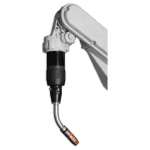
PRODUCT UPDATE – TOUGH GUN TA3 Torch Solutions for Yaskawa Motoman Robots
PRODUCT UPDATE —
Tregaskiss TOUGH GUN TA3 Torch Solutions for Yaskawa Motoman RobotsOverview
Details
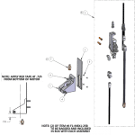
Configuration Comparison

Configuration Tregaskiss Cable Motoman Cable Tregaskiss Spacer: AS-114-13 Solid mount, with or without wire brake Yes No Clutch mount, with our without wire brake Yes No Motoman Spacer: 168535-1 Solid mount, with or without wire brake No Yes Clutch mount, with or without wire brake No Yes Proper Setup – No impact on TCP or cable life

A complete Tregaskiss setup consists of all Tregaskiss branded components. The torch spacer will be aluminum and approximately 4-3/8″ in length. The cable will have a corrugated hose from front to back.
A hybrid Tregaskiss/Motoman setup consists of a Tregaskiss torch and consumables with a Motoman spacer and cable. The spacer will be approximately 2-3/8″ in length. The cable will have a loose spring from front to back.Improper Setup – Negative impact on TCP and/or cable life

Installing a Tregaskiss cable on a system with a plastic spacer will result in a cable that is too long. Although this cable can be physically installed, this setup will result in premature cable failure.
Installing a Motoman cable on a system with an aluminum spacer will result in a cable that is too short. This cable will not be long enough to plug the power pin into the wire feederTregaskiss Spacer and LSR Unicable Part Number Reference Chart
Robot Make Robot Model Mount Style Tregaskiss Spacer LSR Unicable Part Number No Options Air Blast Wire Brake Air Blast + Wire Brake Motoman® EA1400 XRC Solid Mount N/A 58SM016A 58SM016W 58SM016AW Motoman EA1900 XRC N/A 58SM017 58SM017A 58SM017W 58SM017AW Motoman EA1400N, SSA2000, MA1400, VA1400 Solid Mount N/A 58SM001 58SM001A 58SM001W 58SM001AW Motoman MA1440, AR1440, MH12 AS-114-13 58SM035 58SM035A 58SM035W 58SM035AW EA1900N N/A 58SM002A 58SM002W 58SM002AW Motoman MA2010, AR2010 Solid Mount AS-114-13 58SM038A 58SM038W Motoman MA3100 Solid Mount N/A 58SM031 58SM031A 58SM031W 58SM031AW Motoman Motoman AR1730, MH24 Solid Mount AS-114-13 58SM039A 58SM039AW Motoman EA1400 XRC N/A 58CM016 58CM016W 58CM017 58CM017A 58CM017W 58CM017AW Motoman EA1400N, SSA2000, MA1400, VA1400 Clutch N/A 58CM001 58CM001W 58CM001AW MA1440, AR1440, MH12 Clutch AS-114-13 58CM035A 58CM035W 58CM035AW EA1900N Clutch N/A 58CM002 58CM002A 58CM002W Motoman MA2010, AR2010 Clutch 58CM038 58CM038A 58CM038W 58CM038AW Motoman MA3100 N/A 58CM031 58CM031A Motoman MA3120, AR3120 AS-114-13 58CM032AW Motoman AR1730, MH24 Clutch AS-114-13 58CM039 58CM039A 58CM039AW
IMPORTANT!
NEW PRODUCT – C Series Handle Option for BTB MIG Guns
NEW PRODUCT –
C Series Handle Option for BTB MIG GunsNew C Series Straight Handle

Tips for Maximizing Welding Operator Comfort and Productivity
Tips for Maximizing Welding Operator Comfort and Productivity

Selecting the right gas metal arc welding (GMAW) gun
Amperage:
Handle:
Trigger:
Neck:
Power cable:
Consider gun balance

Customize for the job
Use correct positioning and form
Maximizing comfort
Best Practices for Success in Self-Shielded Flux-Cored Welding
Best Practices for Success in Self-Shielded Flux-Cored Welding

Slag inclusions
Porosity
Wormtracking
Two additional defects affecting weld quality are lack of fusion and undercutting. Preventing these issues can help welding operations save time and money in rework and downtime. Problems with penetration
Finding success
Tregaskiss Offers Online Configurator for Robotic Nozzle Cleaning Stations
Tregaskiss Offers Online Configurator for Robotic Nozzle Cleaning Stations

Understanding Gun Ratings: What You Need to Know to Select Your MIG Gun
Understanding Gun Ratings: What You Need to Know to Select Your MIG Gun

Gun ratings explained
How do you operate?
Understanding the impact of heat
Radiant Heat
Resistive Heat
As an air-cooled MIG gun increases in amperage, the size of the cable, connections and handles also increases. Therefore, a MIG gun with a higher rated capacity almost always has greater mass. If you are an occasional welder, that weight and size increase may not bother you; however, if you weld all day, every day, it is better to find a lighter and smaller MIG gun suited to your application. In some cases, that may mean switching to a water-cooled MIG gun, which is smaller and lighter, but can also provide the same welding capacity. Deciding between air- and water-cooled
Final thoughts to keep you comfortable
Considerations for Consumables in Robotic Welding Applications
Considerations for Consumables in Robotic Welding Applications
Space and duty cycle factors

Consumable materials and sizes
good defense against premature consumable
failure and poor shielding gas coverage,
and can help extend the life of front-end
consumables.Heavy- versus standard-duty
Welding mode and wear
Consider the impact of welding wire
Maintaining Consumables
New Reverse Part Number Lookup Function for Online MIG Gun Configurators Saves Time
New Reverse Part Number Lookup Function for Online MIG Gun Configurators Saves Time

Gain Efficiencies and Extend Consumable Life with Anti-Spatter Compound
Gain Efficiencies and Extend Consumable Life with Anti-Spatter Compound
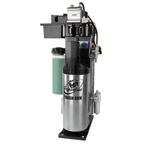
Although it resembles water in its consistency, anti-spatter compound (when applied correctly and in the appropriate volume), will not drip like water. It simply creates a sacrificial barrier between the nozzle and any spatter generated during the welding process; the spatter easily falls off when the nozzle cleaning station performs the reaming cycle, thereby leaving the nozzle and other front-end consumables clean. The compound must be reapplied frequently to help maintain that barrier. tt
Positioning the robotic GMAW gun and front-end consumables in the correct location for the ream cycle and anti-spatter application helps the compound to be applied uniformly. To gain optimal spray coverage, always follow the manufacturer’s instructions for proper setup based on the nozzle bore size. If the sprayer is too far away from the nozzle, it will not provide adequate coverage to prevent spatter buildup. If the nozzle and sprayer are too close, too much spray may saturate the nozzle insulator, which can lead to premature failure.Adding a spray containment unit
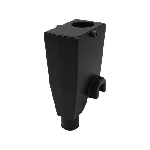
This 3- to 4-inch unit fits over the spray head on the anti-spatter compound sprayer. Additional tips for effective nozzle cleaning station operation
Bernard and Tregaskiss to Attend FABTECH 2016
Bernard and Tregaskiss to Attend FABTECH 2016

Tips for Optimizing Reamer Usage
Tips for Optimizing Reamer Usage
This article has been published as an exclusive with The Fabricator. To read the entire article, provided by Ryan Lizotte, Tregaskiss field technical support specialist, please click here.
Customizing Your GMAW Gun for the Job
Customizing Your GMAW Gun for the Job

This article has been published as a web-exclusive on thefabricator.com. To read the entire story, please click here.
PRODUCT UPDATE – Replacement Parts Availability for the TOUGH GARD Spatter Cleaner
PRODUCT UPDATE —
Replacement Parts Availability for the TOUGH GARD Spatter Cleaner
Discontinued Replacement Parts
Part Number Description PER-2510 Motor
Available Replacement Parts
Part Number Description ER-2241 Control Valve ER-2242 Sprayer Valve ER-2560 Reed Switch ER-2609 Wiring Interface Receptacle ER-2700 Spatter Cleaner Pneumatic ER-500-15 Spray Head PER-220 Valve Assembly PER-2599 Spatter Cleaner Kit (motor not included) PER-2680 Rear Shroud PER-2685 Front Shroud PER-500-15-6 Reservoir Mount
New TOUGH GUN Reamer Stand Offers Customizable Height and Quick Installation at a Lower Cost
New TOUGH GUN Reamer Stand Offers Customizable Height and Quick Installation at a Lower Cost
Getting the Most Out of Peripherals
Getting the Most Out of Peripherals

Clutches
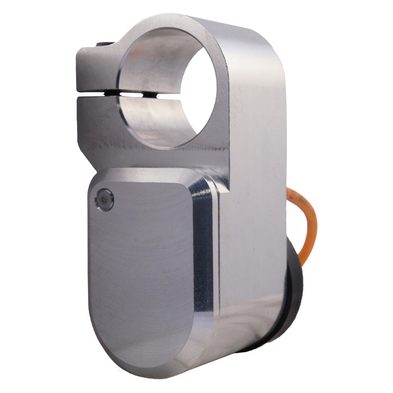
Wire cutters
Neck inspection fixtures
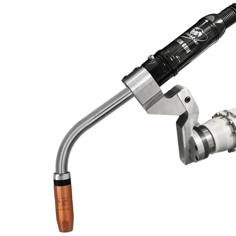
Nozzle cleaning stations and sprayers
No peripheral decision
PRODUCT UPDATE – TOUGH GUN TA3 MIG Gun Offering Available for Panasonic TM-2000
PRODUCT UPDATE —
TOUGH GUN TA3 MIG Gun Offering Available for Panasonic TM-2000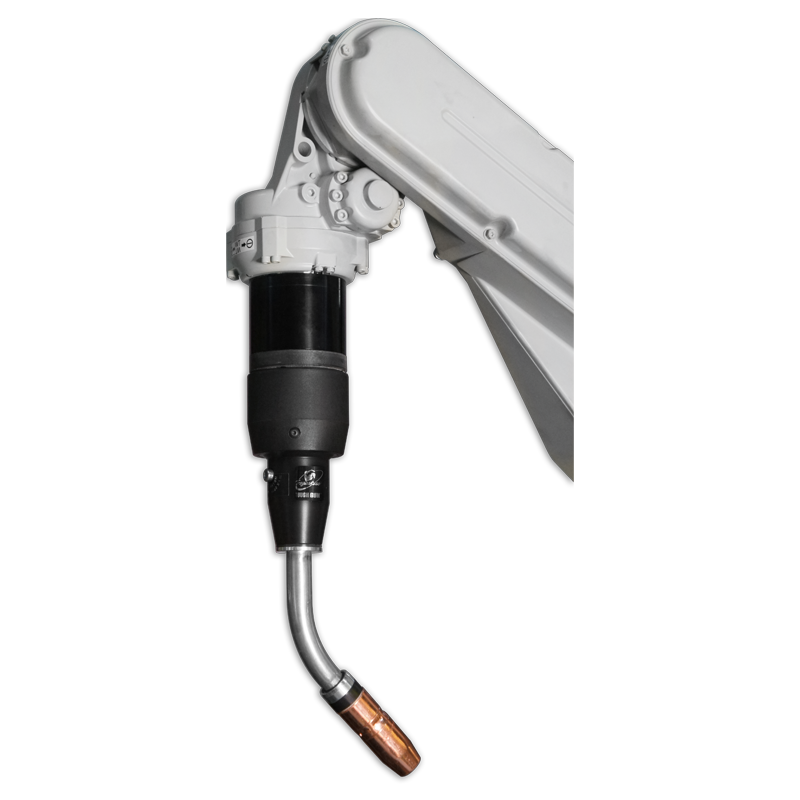
Available Resources
DISCONTINUED PRODUCT – PER-2510 Motor
DISCONTINUED PRODUCT — PER-2510 Air Motor for the TOUGH GARD Spatter Cleaner
Fiam® Air Motor Model Number Part Number 28M100D-3/8-24UNF 185609008
Vendors:
Revised PER-2599 Kit Parts Breakdown

Item Part Number Description Qty Length 1 PER-2511 Motor Clamp Detail 1 3 PER-2611 Spatter Shield Plate, Inner 1 4 F1-M6X1-25B M6x1x25mm LG SHCS, Black Oxide 3 5 F2-M4X.7-6B M4x.7x6mm LG SHCS, Black Oxide 4 7 TR-2231 5/16″ x 1/8″ NPT QC 1 8 ER-2700 ER Reamer Pneumatic Kit 1 Not Shown Red Tape Electrical Red Tape, 18mm Wide 4.5″
Click here to download the archived M075 TOUGH GARD spatter cleaner technical guide. What You Should Know About Robotic MIG Gun Clutches
What You Should Know About Robotic MIG Gun Clutches
7 Tips for Improving MIG Welding
7 Tips for Improving MIG Welding
1. Remember that the best MIG welding operator is a safe one.
2. Do your research before you set up your equipment.
3. Make sure all of your connections are sound before getting started.

4. Select the proper drive roll and tension setting to effectively feed wire.
5. Use the correct contact tip recess for the application.

6. Use the shielding gas best suited to your wire.
7. Keep the wire directed at the leading edge of the weld pool.
Common Causes and Solutions to GMAW Gun Overheating
Common Causes and Solutions to GMAW Gun Overheating

This article has been published as an exclusive with Practical Welding Today on thefabricator.com. To read the entire story, please click here.

![]()