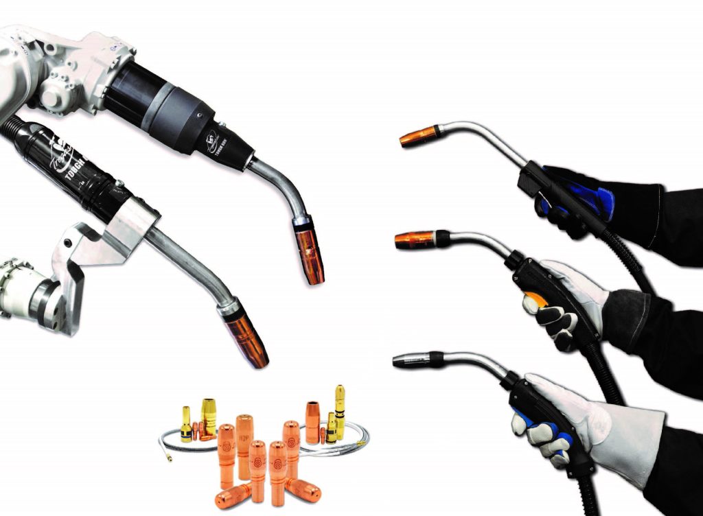
Bernard and Tregaskiss Release NEW MIG Welding Guns & Consumables Catalog
BEECHER, Ill./WINDSOR, Ontario. (March, 2023) — Bernard and Tregaskiss have announced the availability of a joint MIG Welding Guns & Consumables catalog.
The 46-page, full-color catalog includes a consumable comparison chart to compare contact tip, nozzle and diffuser types across the brands’ available consumables offerings, along with a consumables and MIG gun series compatibility chart to guide users in their selection.
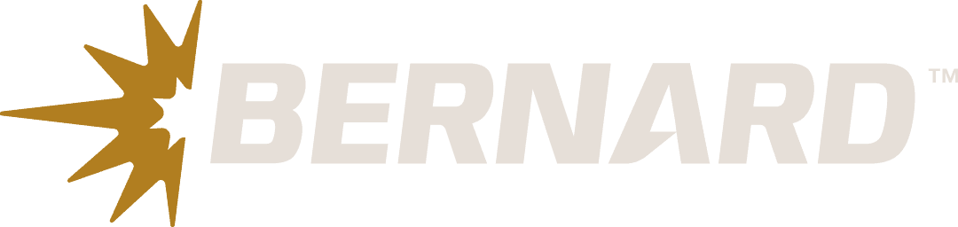
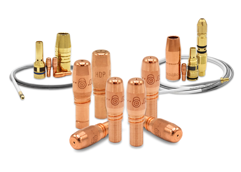
The catalog offes easy-to-read key features and part numbers for its products and is organized by product category, first highlighting the brands’ exclusive AccuLock™ S and AccuLock R Consumables — both designed to reduce downtime and improve welding performance.
Also included in the catalog are product details and configurator overviews for customizing Bernard® Semi-Automatic MIG Guns, Tregaskiss® Robotic MIG Guns, Clean Air™ Guns and more. Tregaskiss Fixed Automatic MIG Guns for hard tooling applications are also featured.
Each page includes website quick links with URLs users can visit to learn more about a specific product, plus service and support contact numbers and directions to explore online resources, such as videos and product configurators.

The catalog can be downloaded as a PDF or ordered as a printed copy at Tregaskiss.com/literature.
Bernard AccuLock S Consumables Now on Select Miller® Packages
Bernard AccuLock S Consumables Now on Select Miller® Packages
BEECHER, Ill. (March 7, 2023) – Bernard has announced that AccuLock S consumables will now be standard on its BTB MIG guns included in select packages from Miller Electric Mfg. LLC. These will replace its Centerfire™ consumables that previously shipped with the equipment.
An AccuLock nozzle and contact tip will be included in these packages, along with a newly designed gas diffuser that is compatible with Bernard conventional liners. This diffuser will simplify conversion of existing fleets of BTB MIG guns from Centerfire consumables or TOUGH LOCK® consumables to AccuLock S consumables. To enjoy the full benefits of the AccuLock S dual-locked liner system, users can choose to upgrade their MIG guns later by changing the diffuser, liner and power pin cap.
The AccuLock S consumables will be standard on the following Miller packages:
- Suitcase® 12RC
- ArcReach® Suitcase 8 and 12 (on Bernard BTB MIG guns only)
- Deltaweld® Systems
- XMT® 350 FieldPro™ Systems
- XMT 450 Systems
- Continuum™ Systems
- 20 Series
- S-74 MPa Bench Feeders
- Intellx™ Wire Feeders
- Intellx Swingarc™
Bernard is providing end users with the ability to configure Bernard BTB MIG guns with AccuLock S consumables for conventional liner diffusers through its online configurator. Packages that have Dura-Flux™ and PipeWorx guns will not include AccuLock S consumables.
For more information, visit Tregaskiss.com/acculock_conventional/.
# # #
Using Root Cause Analysis to Address Welding Consumable Issues
Using Root Cause Analysis to Address Welding Consumable Issues
Estimated reading time: 4 minutes
Troubleshooting problems with welding consumables can be time-consuming and expensive. From the associated downtime to the cost of replacing contact tips, diffusers, nozzles and liners, companies stand to lose productivity and potentially miss production goals.

Applying root cause tools can help expedite the process. These are structured methods to narrow down the true cause of a problem and determine an exact solution.
At a high level, root cause analysis follows several key steps:
- Defining the problem
- Collecting information
- Identifying issues that are contributing to the problem
- Determining the root cause
- Recommending and implementing the solution
To successfully implement root cause tools, it’s important to keep an open mind about possible causes that are contributing to welding consumable problems and to be patient, as it may take time to determine a cause and solution. Analytical thinking, along with being thorough and unbiased in the assessment, is a must.
The 5 Whys
The 5 Whys is a common and simple root cause tool to apply to welding consumable issues. It involves asking “Why?” five times, and providing answers, to drill down to the root cause. In some instances, the solution may become apparent after fewer than five questions. Other times, it may take more. It is also possible that the questioning may become circular and require branching off into another line of questions. Once the root cause is identified, companies can home in on the right solution and determine ways to prevent further problems.
For example, companies may ask the following if there are issues in a semi-automatic welding operation:
- Why do we have an erratic arc? Because the welding wire is feeding poorly.
- Why is the welding wire feeding poorly? Because the wire feeding path is blocked.
- Why is the wire feeding path blocked? Because the liner is kinked up.
- Why is the liner kinked up? Because it was trimmed incorrectly.
- Why was the liner trimmed incorrectly? Because welding operators didn’t measure it properly
Knowing this information, companies may determine they need to train welders to use a liner gauge during trimming and installation. AccuLock™ S consumables are another option, as these have a liner that eliminates liner trim length errors without the need to measure. The liner locks and aligns at the front and back of the gun to provide a flawless wire feed path.
To gain the best results from The 5 Whys, engage employees who have hands-on experience with the welding process. Quality engineers are also great resources to include.
Failure Modes & Effects Analysis (FMEA)
FMEA assesses how a failure could occur, its causes and what the potential consequences of a failure would be. FMEA follows the same logic as The 5 Whys to drill down to a root cause. Engineers use this tool proactively during the design of components like welding consumables. Companies can also use FMEA over the course of using these products as a troubleshooting method.
Keeping with the example of welding consumables, a FMEA for troubleshooting may look like this in a robotic welding operation:
- Failure mode: Off-location welds.
- Potential consequence: Non-conforming parts.
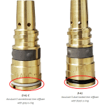
- Potential cause: Cross-threaded contact tip.
- Current process controls: Train employees to install contact tips correctly.
Potential solution: Use a contact tip that can’t be cross-threaded. These can be found in the AccuLock R consumables system.
When using FMEA or The 5 Whys to troubleshoot welding consumables issues, it’s important to look at all aspects of the situation to accurately determine the root cause. While it may seem time-consuming, investing in the use of these methods can actually save time in the long term — not to mention frustration and costs.
PRODUCT CHANGE — AccuLock™ Conventional Liner Gas Diffusers
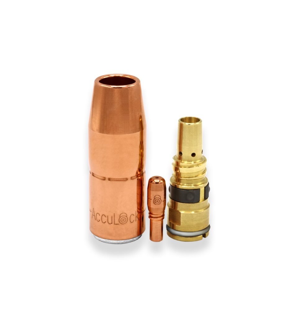
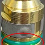
PRODUCT CHANGE — AccuLock™ S Conventional Liner Gas Diffusers — O-Ring Color Change to Gray
All AccuLock S conventional liner gas diffusers began shipping with a gray o-ring instead of a black o-ring on February 22, 2023. The gray o-ring makes it easier to tell the difference between an AccuLock S dual-locked liner gas diffuser and an AccuLock S conventional liner gas diffuser.

For reference, the AccuLock gas diffuser part numbers listed below will be assembled with a gray o-ring:
| Part Number | Description |
| D-A1-C | AccuLock S Gas Diffuser, Large Nozzle, Thread-On, Conventional Liner |
| D-A2-C | AccuLock S Gas Diffuser, Large Nozzle, Slip-On, Conventional Liner |
| DS-A1-C | AccuLock S Gas Diffuser, Small Nozzle, Thread-On, Conventional Liner |
| DS-A2-C | AccuLock S Gas Diffuser, Small Nozzle, Slip-On, Conventional Liner |
Welder Training Tips to Help Improve Productivity
Welder Training Tips To Help Improve Productivity
Estimated reading time: 6 minutes
Improving productivity in semi-automatic operations isn’t simply about welding faster and working harder. Instead, there are ways to create consistency in the process and support quality so that companies can avoid downtime that adversely affects throughput.
When training new welders, it’s important to provide a solid foundation of knowledge to achieve the best results. Taking the time to establish and expand welders’ skill sets shows welders companies are invested in them, and as welders gain more experience, they become more confident. The aim is to empower them and provide all the information necessary to be productive.
To instill good habits from the start, consider some key training tips.

Put safety first
A safe welder is a productive welder. By training new welders to follow welding safety protocols, there is less risk of lost productivity due to injury. Wearing the appropriate personal protective equipment (PPE) is important. This includes a properly fitted helmet, safety glasses, flame-resistant jacket or sleeves, welding gloves and steel-toed, rubber-soled boots. If the process is prone to higher levels of fume generation, correct use of a respirator is necessary. Train welders to read and follow all equipment labels and their owner’s manual carefully before operating welding equipment. Training also includes checking the power source ground, securing workpieces in the best possible manner and keeping their heads out of the weld plume when welding.
Establish consistent weld prep
Following best practices for weld prep supports high weld quality, reduces rework and scrap, and improves productivity. As part of new welder training, welders should understand their power source settings, type and levels of the shielding gas being used, and how to clean the base material. Checking that all welding consumable connections are tight can minimize electrical resistance that could lead to burnbacks (the formation of a weld in the contact tip) and downtime for tip changeover.
Install welding consumables correctly
Downtime to address liner issues is common in semi-automatic welding operations and is typically caused by incorrect installation. This can lead to bird-nesting (a tangle of wire in the drive rolls), poor wire feeding, an erratic arc, wire chatter, burnbacks and more. Always use a liner gauge when trimming a liner; or consider a consumable system like AccuLock™ S, which provides error-proof liner installation without measuring. The liner locks and is aligned to the power pin and the contact tip to ensure proper wire feeding. New welders should also learn to install and tighten contact tips according to the consumable manufacturer’s recommendation.
Focus on comfort
Training welders to pay attention to their posture and the angle they hold their MIG welding gun can help reduce fatigue and the risk of welding-related musculoskeletal disorders that lead to lost productivity. Whenever possible, welders should position themselves so they are welding the workpiece in the range between their waist and shoulders. This may require a work stool or adjustable chair. Welders should also keep their hands and welding gun at or slightly below elbow height. Gaining good visibility to the weld joint can encourage proper posture.

Follow welding procedures
Welding procedure specifications (WPS) are a means to create consistency in the welding operation by taking the guesswork out of the process. This document outlines welding parameters, filler metal type and diameter, wire feed speed (WFS), weld pass sequence and more. Training new welders to follow the details in a WPS can help ensure that they produce quality welds and remain productive.
Use the right equipment
New welders should be trained to use the best equipment and tools for the job — and ones that best suit them. A MIG welding gun that fits the welder’s hand comfortably will help maximize their time when welding. Using a hammer for repositioning a part, as opposed to the MIG gun itself, can prevent damage to the gun that leads to downtime for repairs or replacement.
Likewise, having the correct wrench for installing gas diffusers or welpers for tightening contact tips helps ensure snug connections and lessens the opportunity for issues. Using the wrong tools or not tightening parts properly leads to loose connections that cause electrical resistance. This, in turn, increases heat and wears out the equipment prematurely.
Employ proper techniques
Welding techniques vary according to the process, the welding position and the thickness of the base material. For example, when MIG welding with solid or metal-cored wire, welders need to learn to use a push technique, while a flux-cored process requires a drag technique. Train welders on the proper gun angles for flat, horizontal and out-of-position welding applications so they are able to fill the joint with the appropriate amount of weld metal and avoid issues like lack of fusion.
Recognize signs of trouble
Training new welders to quickly identify issues in the welding process can minimize downtime for troubleshooting. They should be given the guidance to identify the causes of common problems like porosity, burnbacks, poor deposition and more, along with their solutions. Welders should also be able to recognize signs that equipment needs to be repaired or replaced — for example, a welding contact tip that is keyholing (wearing at the bore unevenly) or a gun that has nicks in the power cable. Companies can provide troubleshooting cards with quick checklists to keep in the weld cell as reminders.
Keep communication open
Clearly communicating expectations to new welders and having supervisors who are responsive to questions are vital parts of training. It is about both learning and listening. As training continues and welders grow their skill sets, it’s important to establish two-way feedback. This way everyone can find common ground on what best practices could be. In some cases, new welders may identify a way to improve the operation based on experience they have from another job.
Successful new welder training
When companies commit to providing thorough new welder training, the aim is to establish skills that lead to consistency in quality and reduce downtime. The more they can avoid secondary work or additional processes, the better productivity will be. Plus, supporting the comfort and safety of welders can help make sure they perform their best every day, build confidence and help retain them as employees.
At a Glance: Cobots and the TOUGH GUN® CA3 MIG Gun
At a Glance: Cobots and the TOUGH GUN® CA3 MIG Gun
Estimated reading time: 4 minutes
Companies today continue to face a shortage of qualified welders, but the demand for product has stayed the same — or in many cases, increased. Turning to new solutions to keep up with production can help keep the welding operation running smoothly and quickly.

For many companies producing a high mix and low volume of parts, investing in a cobot can be a smart business decision. A cobot, or collaborative robot, relies on interaction from a welding operator but provides faster speeds than semi-automatic welding. Cobot welding is also a less expensive alternative to robotic welding and takes up less space.
To operate the cobot, the welding operator uses a tablet to program the desired weld and moves the cobot welding gun to the beginning of the joint. While the cobot is welding, the welding operator can work on other activities, helping companies make the most of the available labor.
Tregaskiss TOUGH GUN CA3 robotic air-cooled MIG gun
Tregaskiss designed its TOUGH GUN CA3 to help companies gain the most from their cobot. It provides several key benefits.
Durability
The TA3 gun is designed and engineered with the same trusted and robust components as other Tregaskiss guns and is proven to last in high-volume welding operations.
Productivity
Combined with AccuLock™ R consumables, the TOUGH GUN CA3 welding gun can help ensure greater productivity. The contact tips last longer so there is less downtime for changeover. When routine changeover is necessary, it can be done quickly and easily so the cobot and welding operator spend more time producing parts.
Reliability
The TOUGH GUN CA3 MIG gun has metal-to-metal keyed connections to hold it in place in the mounting arm. These also keep the aluminum-armored neck firmly connected to the gun, so users can depend on the gun to perform consistently.
Simplicity
The gun is easy to maintain when needed — necks can be changed with one tool by loosening a small number of fasteners. Operators can also easily install QUICK LOAD® liners from the front of the gun. For operations that have semi-automatic welding, companies can streamline inventory by using the same AccuLock contact tip on their MIG guns.
Compatibility
The CA3 gun is compatible with cobots from FANUC®, Yaskawa® Motoman® and Universal Robots (UR) and most welding power sources. Power pin options are available for machines from Miller®, Lincoln®, Fronius®, Tweco®, Panasonic® and more.
Tregaskiss offers customizable options according to style and neck, consumables, cable length, wire size and power pin through the online configurator.
Cobot welding best practices
Along with having a reliable cobot MIG gun, there are some best practices to consider for cobot welding.
- Provide welding operators with proper training. Programming is relatively easy using a simple tablet interface, and training can be done quickly. In many cases, welding operators are able to share their knowledge with other employees to expedite training.
- Follow safety precautions and use proper Personal Protective Equipment (PPE). Read and follow the cobot and cobot gun owner’s manuals. The cell where the cobot is located should be surrounded by welding curtains to protect the operator and others from arc flash.
- Tooling, fixtures and other equipment added to the robotic cell after delivery may change the type and number of hazards present in and around the cobot system. Conduct a safety review and perform another risk assessment after the installation of any additional equipment to the robotic cell.
- Understand the rating of the gun and make sure that it is appropriate for the application and prevent overheating. The CA3 gun offers 350 amps at 100% duty cycle with mixed gases.
- Be sure the robot and gun can move freely and that the power cable doesn’t interfere. Operators should also stand clear of the moving cobot.
- Understand the tool center point (TCP) and how far the cobot and cobot gun can reach to ensure quality.
As with any welding application, contact a trusted cobot welding gun or cobot manufacturer with questions or reach out to a local welding distributor.
PRODUCT CHANGE — CONE NUT AND END FITTING
PRODUCT CHANGE — CONE NUT AND END FITTING ON BERNARD® BTB MIG STRAIGHT HANDLE MIG GUNS WITH HYTREL® POLYMER CABLE — EFFECTIVE JANUARY 3, 2023
Our product offering is regularly assessed to ensure focus on customer needs and opportunities to innovate our product portfolio, so we can continue to deliver sustainable value to our customers.
Starting 1/3/2023, there will be part number changes to the cone nut/end fitting found on Bernard BTB straight handle MIG guns with Hytrel polymer cable. Note that although the parts will look different, the functionality remains the same. These part number changes are also reflected in the current BTB MIG Gun Owners Manual.

| Current Part Number | New Part Number | Type |
| 308 | 1680087 | End Fitting |
| 408T | 1680088 | End Fitting |
| 409 | 1540003 | Cone Nut |
| 509 | 1540004 | Cone Nut |
| 608-1 | 1680089 | End Fitting |
| 609 | 1540004 | Cone Nut |
Should you have any questions or need further assistance, please contact your local ITW representative.
5 Tips for Improving Weld Quality
5 Tips for Improving Weld Quality
Estimated reading time: 7 minutes
Establishing consistent levels of weld quality is important for attaining production goals and a better bottom line in semi-automatic welding operations. However, there are many factors that can negatively impact those efforts, including a lack of skilled labor, inadequate or aging equipment or using the wrong welding consumables.

To avoid costly rework associated with poor weld quality, it’s critical to implement proper welder training. Evaluating the welding operation on a regular basis for issues can also help, along with following these key tips.
No. 1: Size contact tips correctly
Welding contact tips are available in a range of diameters — typically 0.023 to 1/8 inches — to accommodate different welding wire sizes. The wire packaging, in part, determines what size contact tip is appropriate to support good weld quality.
Welding wires in larger drums — 500 pounds or more — have a larger cast and are flatter so there is less degree of arc. This means there is less opportunity for the wire to make consistent contact when feeding down the bore of the contact tip, resulting in an erratic arc and weld quality issues. To avoid problems when using copper and chrome zirconium welding contact tips (with Bernard and Tregaskiss consumables), undersize them for the diameter of wire. For example, match an 0.045-inch wire to a 0.039-inch contact tip. For other manufacturers’ contact tips, request recommendations.
Copper and chrome zirconium contact tips can be matched size for size with wire on spools or in drums less than 500 pounds since the wire has a tighter cast.
For AccuLock™ HDP contact tips, the wire and tip size can be matched regardless of the welding wire drum or spool size.

No. 2: Size and change over liners properly
As with contact tips, welding liners are available in various diameters and ranges, from 0.035 to 0.045 inch or from 0.045 to 1/16 inch. To avoid issues like burnback (the fusing of a weld in a contact tip), poor wire feeding and an erratic arc that can be detrimental to weld quality, match the diameter of welding wire to that of the liner. This supports the wire as it feeds through the liner.
It’s equally important to trim the liner properly. A liner that is too short can create wire chatter, an erratic arc and bird-nesting (a tangle of wire in the drive rolls). If the liner is too long, it can cause the wire to weave. Both situations can cause poor welds and, potentially, rework.
Always use the gauge provided by the manufacturer to ensure that the liner is trimmed correctly. The AccuLock S consumable system is also a good option, as it provides error-proof liner replacement. The liner loads through the neck at the front of the gun and is locked and trimmed flush with the power pin at the back of the gun, which eliminates the need to measure.
No. 3: Keep electrical resistance low
Electrical resistance — or interference with the flow of electricity in a semi-automatic MIG gun’s circuit — generates heat and can impede weld quality by negatively impacting the gun’s components. There are several causes that can be rectified to prevent issues such as inconsistent weld appearance or an erratic arc.
Through ongoing use, connections begin to wear and loosen, leading to electrical resistance. Address this problem by tightening connections between the gas diffuser, gun neck and handle, as well as the connections from the power cable to the power pin and wire feeder.
Power cable wear that results in hotspots can also lead to electrical resistance. This wear may not always be visible, so as a course of troubleshooting, operators should consider this problem as a cause of poor weld quality. Replace the cable as necessary to prevent issues. Likewise, increased electrical resistance can occur in the gun handle, since it is an area of high use and bending. Look for signs of wear and replace as needed.

No. 4: Be mindful of cleanliness
There are various aspects of cleaning and weld prep that can help support good weld quality. Always follow proper procedures for cleaning the base material to prevent defects like porosity that can be caused by welding through dirt, oil and debris.
It’s also important to be proactive about cleaning consumables. For example, weld spatter buildup in the nozzle or in the ports in the gas diffuser can hinder shielding gas coverage, which also leads to porosity. Clean or replace these consumables when excessive spatter is evident. Operators can also apply anti-spatter compound to the consumables by dipping the front inch and a half of the nozzle into the liquid. Use the anti-spatter compound sparingly to avoid damaging the nozzle insulator.
Storing consumables in a clean area minimizes the opportunity for dust, oil or other contaminants to adhere to the surface of the welding contact tip, nozzle and diffuser and adversely affect weld quality. A covered container with compartments for each welding consumable is a good option to protect them.

Also consider how to handle the welding liner during changeover. Be careful not to drag the liner on the floor while feeding it into the gun, since doing so can cause debris to collect on it and be pulled into the gun.
No. 5: Plan for inspection and maintenance
Preventative maintenance and ongoing care of the MIG gun and consumables can go far in supporting high weld quality. Set a schedule to inspect, maintain and repair the components.
Although often overlooked during regular inspections, the O-rings found throughout the gun are important to assess. If they start to degrade or break, they can cause shielding gas leaks that lead to porosity and potentially extra costs for shielding gas if the operator increases gas flow to compensate for the leak. Check O-rings on the power pin, gas diffuser and liner during routine preventive maintenance and replace these components as needed.
Look for damage to the power cable, such as nicks or tears that can impede gas flow. Visually inspect the gun handle for cracks or missing screws and the trigger for sticking or malfunction. Repair or replace as necessary.
Last, inspect the welding contact tip for keyholing (an oblong wear of the bore); this can cause drifting wire and arc start failures that affect weld quality.
Long-term results
Improving weld quality is a matter of ongoing evaluation. Supervisors and managers overseeing semi-automatic welding operations should regularly consult with welding operators to make sure they are following best practices. Ongoing training and quickly troubleshooting issues can also support good weld quality and prevent costly downtime and rework.
Is a Water-Cooled Robotic Welding Gun Necessary?
Is a Water-Cooled Robotic Welding Gun Necessary?
Robotic welding operations can be tough on equipment. The heat from the welding arc, along with reflective heat from the base material and resistive heat from the electrical components, can wear on consumables and the robotic welding gun. In some cases, implementing a water-cooled robotic MIG gun is the answer, but many times an air-cooled model can handle the job.

Water-cooled robotic welding guns are designed to handle high amperage applications, typically above 400 welding amps at 100% duty cycle. They are used for longer welds and multiple passes on thicker material with larger welding wire diameter (above 0.052 inch), such as those found in heavy equipment manufacturing.
That said, water-cooled guns are more expensive upfront compared to their air-cooled counterparts and require the additional expense of a water cooler. These guns operate by circulating a coolant from the water cooler through hoses in the power cable to the gun and neck, then returning the coolant to the cooler to release the absorbed heat. Due to the complexity of this design, there are more potential failure modes, so maintenance and repairs cost more over the life of the gun. Given the current shortage of skilled labor, it can be difficult to find welding operators who can take on these tasks. That can lead to downtime and lost productivity.
For these reasons, companies need to ask: Is a water-cooled welding gun necessary? Often, companies may be using this type of gun because it’s what’s always been on the plant floor, or they think they need the extra protection from the heat of the application. They may even be trying to protect the consumables from overheating. That doesn’t mean that a water-cooled welding gun is the best option.
When air-cooled makes more sense
Air-cooled robotic welding guns use the ambient air, shielding gas and arc-off time to dissipate heat. Their design is simple and easy to maintain since they have fewer parts than water-cooled models. A lower upfront cost and less expense to care for the guns make them an appealing alternative to a water-cooled gun. And, in several instances, these guns are a better option for a welding operation.
Duty cycle factors into using an air-cooled robotic welding gun. Duty cycle refers to the number of minutes a welding gun can operate at full capacity in a 10-minute period without overheating. If the gun can operate the full 10 minutes, then it offers 100% duty cycle. However, many applications do not require 100% duty cycle and therefore wouldn’t benefit from a water-cooled gun that offers that capacity. In this case, it is possible to use a 350-amp air-cooled gun and run it at a lower duty cycle: for example, 50%. An air-cooled robotic MIG gun will heat up and plateau at a certain temperature. The operator overseeing the application will need to be cognizant of the duty cycle and welding duration and adjust the application accordingly.
In applications with shorter weld requirements, it’s also possible to configure a robotic welding cell to use air-cooled robotic welding guns. On a robotic line, there are often multiple robots welding at the same time. If one robot only welds for one minute and a second robot welds for two minutes, then the air-cooled gun on the first robot has time to cool down as it waits for the other robot to finish its weld. In essence, the robotic welding gun on the first robot would be working at 50% duty cycle as compared to the second robot.
For companies using a water-cooled robotic MIG gun to keep consumables from overheating, a simple change of consumable type combined with an air-cooled gun is a better, and less costly, option. Consider changing from a copper contact tip to a chrome zirconium, since it can withstand heat better. Also, high-performance consumables like AccuLock™ HDP contact tips can significantly extend tip life, even in hard pulsed robotic welding applications. They can last six to 10 times longer than copper and chrome zirconium tips. While these contact tips have a higher upfront cost, the lower expense of an air-cooled robotic welding gun means the reduction in downtime and higher productivity saves money in the long term.
Simplifying the robotic welding operation
The goal of investing in robotic welding is to increase productivity, improve quality and reduce costs. Using an air-cooled robotic welding gun, when possible, can help companies gain these benefits. The lower upfront cost and total cost of ownership of this equipment means a better bottom line.
From Consumables to Communication: Reducing Human Error in Welding
From Consumables to Communication: Reducing Human Error in Welding
Estimated reading time: 4 minutes
Human error can take its toll on welding operations, leading to downtime and lost productivity, poor quality and increased costs. It can result from a variety of factors. An operator may know how to manage a process, but periodically misses a step or forgets to complete a task. Or an operator may believe he is conducting a task in the correct manner, but it is wrong.

To reduce problems, it’s important to provide proper training to semi-automatic and robotic welding operators. This includes not only training on the welding process, but also on how to spot errors when they occur.
Companies may want to rely on principles of poka-yoke to help. These principles could be applied in several ways in a welding operation.
- Elimination: Remove or change parts of the welding process that cause problems
- Prevention: Investing in equipment or processes that prevent errors
- Replacement: Substitute consumables with ones that are more consistent
- Facilitation: Streamline operations to reduce the risk of a welding operator causing an error
- Detection: Identify errors early and correct them before they lead to costly rework
- Mitigation: Find ways to reduce the impact of errors on the welding operation
With these high-level, error-proofing ideas in mind, it’s possible to put them into action in several specific ways.
Color-coded parts
Investing in welding consumables with color-coded parts can help eliminate confusion during installation. AccuLock™ S liners and power pin caps are color coded to make it easy to identify which power pin cap is compatible with which liner. For example, power pin caps with red washers are compatible with liners that have red shrink tube and so on.
Welding procedures
Implementing a welding procedure specification (WPS), and training operators to follow it, can help ensure consistent, high-quality welds. A WPS outlines details on the welding process and parameters, weld pass sequences, filler metal type and size, and more.
Error-proof consumables design
For operations with a mix of welding arcs or for all automated welding operations, AccuLock R consumables are designed to prevent errors associated with cross threading during installation. They feature a long contact tip tail that aligns in the diffuser prior to the thread engaging. This allows operators to install the tip easily and accurately. The AccuLock S welding gun liner also offers error-proof liner trimming with no measuring required for semi-automatic welding operations.
Long-lasting consumables
Consumables that last longer require less changeover, which means less interaction by the welding operator in the welding cell and less potential for errors. AccuLock contact tips offer a longer lifespan, particularly the AccuLock HDP tips. These last up to ten times longer than standard contact tips and are designed for use in pulsed MIG welding applications, where waveforms tend to be harsher on tips.
Inventory reduction
Taking steps to simplify inventory by having a lower variety of consumables can help prevent errors during changeover. The AccuLock S and AccuLock R consumable systems share a common contact tip, so the tip can be used in Bernard semi-automatic MIG guns and Tregaskiss robotic and fixed automatic guns.
Communication and reporting
Keeping open lines of communication among welding operators and with management is an important way to minimize and rectify errors. Knowing what is expected in the welding process is a good start, as is reporting errors when they occur so that they can be fixed and don’t lead to further complications.
Preventing errors in a welding operation requires attention to detail, a commitment to making improvements, and collaboration among welding operators and management. Everyone needs to take a vested interest in the process, knowing that it will help improve quality and productivity — and ultimately make everyone’s job easier.
Choosing Between Fixed Automatic, Cobot and Robotic Welding
Choosing Between Fixed Automatic, Cobot and Robotic Welding
Estimated reading time: 5 minutes

No doubt manual, or semi-automatic, welding has its place across the industries — general fabrication and manufacturing, shipbuilding and more — and it will continue to be an important process for many applications. There are times, however, when companies need to turn to welding automation to augment or replace portions of their operations. Some may benefit from fixed welding automation, while other operations lend themselves to either cobot welding or automated (robotic) welding.
At a high level, companies tend to move to one of these types of welding processes for similar reasons: to improve quality, increase welding productivity and/or lower costs. Some companies may be responding to an increase in demand from customers or want to gain a competitive edge by supplementing their operations with automation. In certain cases, companies may replace some semi-automatic welding cells, shifting welding operators to oversee the automated operation. These systems always require interaction with an operator for loading and unloading parts, programming and troubleshooting when necessary.
To implement the right solution and successfully operate it requires careful planning. A robotic integrator or equipment manufacturer can help, and they can also provide a thorough calculation to help determine the expected return on investment (ROI).
So, when is it time to add an automated welding solution? And which one is the best for a given application?
Fixed automation
Companies that find themselves with very large parts that are difficult to weld in a timely or repeatable manner with a semi-automatic process may want to consider fixed welding automation. This process is well suited to high-volume operations with a low variety of parts, such as structural beams or railcars requiring long, continuous welds or pipe that requires circular welds. The investment in fixed welding automation equipment is relatively low, but it can provide a reliable payback by increasing productivity.
Companies can choose from two options:
- Tooling that holds the part in place combined with a fixed automatic welding gun that moves the length of the weld joint on a track. This is a good option for long, linear welds.
- A fixed automatic welding gun held in place by tooling while the part moves. This setup works well for pipe, which can be rotated.
Because there isn’t a lot of flexibility with tooling, companies investing in fixed welding automation need to consider their long-term plans and the parts they will produce.
Cobot welding
Companies seeking greater versatility in their high-mix, low-volume operations or those needing to produce longer welds than possible with a semi-automatic process could benefit from cobot welding. Those who are interested in the faster speeds associated with welding automation but have limited space or capital to invest may also want to consider the switch. Cobot welding systems are less expensive than robotic welding systems, have a smaller footprint and don’t require the guarding that a robot would.

Since a welding operator works side by side with the cobot, he or she can be in the cell with the equipment with a relatively low safety risk. Cobots are also portable, allowing companies to address multiple applications in the facility without the need to invest in additional equipment.
Training requirements are minimal compared to robotic welding, with straightforward programming on a tablet, and setup is relatively quick. These factors are important for companies struggling to find and retain skilled labor and those seeking productivity increases.
During operation, the operator sets the cobot welding gun at the starting point to put the welding in motion. The cobot is designed to complement the work that the welding operators are doing and allows them to attend to other tasks like grinding while the cobot is welding.
Robotic welding
When a company is falling short of its production goals, experiencing weld quality issues or facing increased customer demands, it may be time to invest in a robotic welding system. While smaller operations can benefit from this process, robotic welding systems especially excel at high-volume, low-variety applications. The facility must have the appropriate space available; robotic welding cells typically take up more room than a cobot or a semi-automatic welding cell.

An advantage of robotic welding, in addition to speed and repeatability, is the relatively quick ROI. To gain that, however, it’s important that the parts coming from upstream are consistent — gaps or poor fit-up can hinder the operation — and that there are no bottlenecks that would make the robot stay idle. An electronic CAD model of the part can help determine if a part lends itself to repeatability.
As with fixed welding automation and cobot welding, it’s imperative to have a welding operator involved with a robotic welding system. Parts need to be loaded and unloaded, and the robot requires programming. Robot integrators and manufacturers typically offer training to help ensure success.
Making the switch
Whether a company is a candidate for fixed welding automation, cobot welding or robotic welding, taking the time to carefully plan for the investment is important. Look to a trusted welding distributor, robot integrator or equipment provider for assistance and for help determining the expected payback.
Product Improvement – LSR+ (Plus) Unicables
PRODUCT IMPROVEMENT –
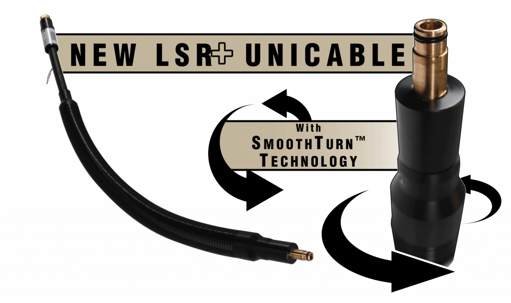
LSR+ Unicables with SmoothTurn™ Technology
October 11, 2022
For use with TOUGH GUN® TA3 ThruArm® series robotic MIG guns, LSR+ (Low-Stress Robotic) unicables incorporate new SmoothTurn™ technology to maximize production uptime.
Conventional style unicables typically come with a connection that limits rotational capabilities and produces torsional stress in the cable. Unlike conventional unicables, the LSR+ incorporates a rotating power connection that reduces this stress during rotation. Additionally, a protective external conduit contributes to cable longevity by shielding components from harsh welding environments.
Stress Relieving Features
- SmoothTurn Technology reduces frictional forces on internal components increasing overall cable life up to 300%
- Enhanced electrical connections provide a more stable arc, resulting in less spatter and longer cable life
- Unique internal components improve support and bend radius of the cable during heavy robot articulation
MIG Welding Basics
MIG Welding Basics
Estimated reading time: 3 minutes
When it comes to MIG welding, it’s important for new welders to start with the basics to set a solid foundation for success. The process is generally forgiving, making it simpler to learn than TIG welding, for example. It can weld most metals and, as a continuously fed process, offers greater speed and efficiency than stick welding.

Welding safety
The very first consideration for new welders is welding safety. It is imperative to read and follow all labels and the equipment Owner’s Manuals carefully before installing, operating, or servicing welding equipment. Welders must wear proper eye protection to avoid arc flash burns and sparks. Always wear safety glasses and a welding helmet set to the appropriate shade level. Proper personal protective equipment attire is also critical to protect the skin from electric shock and burns. This includes:
- Leather shoes or boots.
- Leather or flame-resistant welding gloves
- Flame-resistant welding jacket or welding sleeves
Adequate ventilation is also an important safety factor. Welders should always keep their head out of the weld plume and be sure that the area in which they are welding has adequate ventilation. Some type of fume extraction may be needed. Fume extraction guns that remove the exhaust at the arc are also helpful, and are very efficient compared to floor or ceiling capture.
Welding transfer modes
Depending on base material and shielding gas, welders can weld in various welding transfer modes.
Short circuit is common for thinner materials and operates at lower welding voltage and wire feed speed, so it is slower than other processes. It also tends to produce spatter that requires post-weld cleaning, but overall, it is an easy process to use.
Globular transfer operates at higher wire feed speeds and welding voltages than short circuit and works for welding with flux-cored wire with 100% carbon dioxide (CO2) (see details on CO2 in next section). It can be used on 1/8-inch and thicker base materials. Like short-circuit MIG welding, this mode produces spatter, but it is a fairly fast process.
Spray transfer offers a smooth, stable arc, making it appealing to many new welders. It operates at high welding amperages and voltage, so it is fast and productive. It works well on base materials that are 1/8 inch or more.
Welding shielding gas
In addition to protecting the weld pool from the atmosphere, the type of shielding gas used for MIG welding impacts performance. Weld penetration, arc stability and mechanical properties depend on shielding gas.
Straight carbon dioxide (CO2) offers deep weld penetration but has a less stable arc and more spatter. It is used for short circuit MIG welding. Adding argon to a CO2 mixture allows for use of spray transfer for higher productivity. A balance of 75% argon and 25% is common.
Beyond the basics
Along with practice, knowing some key information can help new welders better understand the MIG welding process. It’s also important to be familiar with the equipment, including MIG welding guns and welding liners. Understanding how to select and maintain this equipment can go far toward establishing good welding performance, quality and productivity.
This is the first article in a three-part series on welding basics. Read article two, MIG Welding Glossary: Terms to Know and article three, MIG Welding Techniques: What to Know.
MIG Welding Glossary: Terms To Know
MIG Welding Glossary: Terms To Know
Estimated reading time: 3 minutes
Welders use MIG welding in many industries — fabrication, manufacturing, shipbuilding and rail to name a few. While it is a common process, it requires attention to detail, and it is helpful to know some key terms associated with it. As with any process, the better the understanding, the better the results.

Bird-nesting
The tangling of welding wire in the drive rolls of the wire feeder. This typically happens when the wire doesn’t have a smooth feeding path due to a liner being cut too short, the wrong size liner or tip being used, or incorrect drive roll settings. Resolve this issue by trimming the liner properly and ensuring that the feed path of the wire is as smooth and straight as possible.
Burnback
Occurs when the wire melts inside the contact tip before reaching the workpiece. It results from incorrect contact-tip-to-work distance (CTWD) — the distance between the end of the tip and the base metal — or a too-slow wire feed speed (WFS). It can also be caused by incorrectly trimmed liner and incorrect parameters. Remedy the problem by increasing WFS, adjusting CTWD, trimming the liner according to the manufacturer’s recommendation and modifying weld parameters.
Deposition rate
Refers to how much filler metal is deposited into a weld joint over a specified period of time, measured in pounds or kilograms per hour (lbs/hr or kg/hr).
Discontinuity
A flaw in the structure of a weld that does not pose a risk of failure. It differs from a weld defect that can affect the integrity of a weld once in service.
Duty cycle
Refers to the percentage of time in a 10-minute period a gun can be used at a specific amperage (arc-on time) without becoming too hot to handle or overheating. A gun’s duty cycle is affected by the type of shielding gas being used for welding. For example, a MIG gun may be rated at 100% duty cycle with 100% CO2 shielding gas, meaning it can weld the entire 10 minutes without issues; or it could have a gun rating of 60% duty cycle with mixed gases.
Electrode extension
The distance the welding wire extends from the end of the contact tip to where the wire melts. As electrode extension increases, amperage decreases, which reduces joint penetration. Also commonly referred to as tip-to-workpiece distance.
Heat-affected zone
Often referred to as HAZ, it is the portion of the base material surrounding the weld that hasn’t melted but has had its properties changed at a microstructure level due to the heat input. Cracking can occur here.
Incomplete fusion
Also called lack of fusion, it occurs when the weld fails to fuse completely with the base material or a previous weld pass in multi-pass welding. Typically, it is the result of an incorrect MIG gun angle.
Porosity
A cavity-like discontinuity that occurs when gas becomes trapped in the weld upon solidification of the molten weld pool. It is most often caused by poor shielding gas coverage or base material contamination.
Weld penetration
Refers to the distance the weld fuses below the surface of the base material. Incomplete weld penetration occurs when the weld doesn’t completely fill the root of the joint.
This is the second article in a three-part series on welding basics. Read article one, MIG Welding Basics and article three, MIG Welding Techniques: What to Know.
MIG Welding Techniques: What To Know
MIG Welding Techniques: What To Know
Estimated reading time: 2 minutes
Understanding some proper techniques for MIG welding can help welders gain good weld quality and avoid the frustration and cost of rework. Everything from proper positioning of the MIG welding gun to travel angle and travel speed can make an impact.

Consider these four recommended techniques:
- While welding, hold the MIG welding gun straight, using both hands to steady it and keeping them at or just below elbow height. This approach not only makes it easier to make a quality weld, but it also helps improve ergonomics. That is particularly important for welders welding for a long period of time, so they can avoid injury.
- Welders should keep a contact-tip-to-work distance (CTWD) of approximately 3/8 to 1/2 inch for short-circuit welding and around 3/4 inch for spray transfer MIG welding.
- Use the proper travel angle. When push welding, welders should hold the gun at a 10-degree angle. This technique creates a wide bead with less joint penetration. For a pull technique, welders use the same angle, pulling the gun toward their body. This results in more penetration and a narrow weld bead.
- Maintain a consistent travel speed with the wire at the leading edge of the weld pool. Too fast of a travel speed creates a narrow bead that may not fully tie in at the weld toes and may lack proper penetration. Traveling too slow creates a wide weld, also with inadequate penetration. Both too slow and too fast travel speeds can cause burn-through on thin base metals.
As with any welding process, practice is a large part of MIG welding success. Along with good techniques, it’s also important to properly prepare and clean the base material before welding and to maintain the MIG welding gun and consumables properly. This can reduce downtime for addressing equipment issues or troubleshooting weld defects and problems such as poor wire feeding.
This is the third article in a three-part series on welding basics. Read article one, MIG Welding Basics and article two, MIG Welding Glossary: Terms to Know.
Solving Common Causes of Welding Porosity
Solving Common Causes of Welding Porosity
Estimated reading time: 7 minutes
Porosity, cavity-type discontinuities formed by gas entrapment during solidification, is a common but cumbersome defect in MIG welding and one with several causes. It can appear in semi-automatic or robotic applications and requires removal and rework in both cases — leading to downtime and increased costs.
The major cause of porosity in steel welding is nitrogen (N2), which gets involved in the welding pool. When the liquid pool cools down, the solubility of N2 is significantly reduced and N2 comes out of the molten steel, forming bubbles (pores). In galvanized/galvanneal welding, evaporated zinc can be stirred into the welding pool, and if there is not enough time to escape before the pool solidifies, it forms porosity. For aluminum welding, all porosity is caused by hydrogen (H2), by the same way as N2 works in steel.

Welding porosity can appear externally or internally (often called sub-surface porosity). It can also develop at a single point on the weld or along the entire length, resulting in weak welds.
Knowing how to identify some key causes of porosity and how to quickly solve them can help improve quality, productivity and the bottom line.
Poor Shielding Gas Coverage
Poor shielding gas coverage is the most common cause of welding porosity, as it allows atmospheric gases (N2 and H2) to contaminate the weld pool. Lack of proper coverage can occur for several reasons, including but not limited to poor shielding gas flow rate, leaks in the gas channel, or too much air flow in the weld cell. Travel speeds that are too fast can also be a culprit.
If an operator suspects poor flow is causing the problem, try adjusting the gas flow meter to ensure the rate is adequate. When using a spray transfer mode, for example, a 35 to 50 cubic feet per hour (cfh) flow should suffice. Welding at higher amperages requires an increase in flow rate, but it’s important not to set the rate too high. This can result in turbulence in some gun designs that disrupts shielding gas coverage.
It’s important to note that differently designed guns have different gas flow characteristics (see two examples below). The “sweet spot” of the gas flow rate for the top design is a lot larger than that of the bottom design. This is something a welding engineer needs to consider when setting up the weld cell.


Also check for damage to the gas hose, fittings and connectors, as well as O-rings on the power pin of the MIG welding gun. Replace as necessary.
When using fans to cool operators or parts in a weld cell, take care that they are not pointed directly at the welding area where they could disrupt gas coverage. Place a screen in the weld cell to protect from external air flow.
Re-touch the program in robotic applications to make sure there is a proper tip-to-work distance, which is typically ½ to 3/4 inch, depending on the desired length of the arc.
Lastly, slow travel speeds if the porosity persists or consult a MIG gun supplier for different front-end components with better gas coverag
Base Metal Contamination
Base metal contamination is another reason porosity occurs — from oil and grease to mill scale and rust. Moisture can also encourage this discontinuity, especially in aluminum welding. These types of contaminants typically lead to external porosity that is visible to the operator. Galvanized steel is more prone to subsurface porosity.
To combat external porosity, be certain to thoroughly clean the base material prior to welding and consider using a metal-cored welding wire. This type of wire has higher levels of deoxidizers than solid wire, so it is more tolerant of any remaining contaminants on the base material. Always store these and any other wires in a dry, clean area of similar or slightly higher temperature than the plant. Doing this will help minimize condensation that could introduce moisture into the weld pool and cause porosity. Do not store wires in a cold warehouse or outdoors.

When welding galvanized steel, the zinc vaporizes at a lower temperature than the steel melts, and fast travel speeds tend to make the weld pool freeze quickly. This can trap zinc vapor in the steel, resulting in porosity. Combat this situation by monitoring travel speeds. Again, consider specially designed (flux formula) metal-cored wire that promotes zinc vapor escape from the welding pool.
Clogged and/or Undersized Nozzles
Clogged and/or undersized nozzles can also cause porosity. Welding spatter can build up in the nozzle and on the surface of the contact tip and diffuser leading to restricted shielding gas flow or causing it to become turbulent. Both situations leave the weld pool with inadequate protection.
Compounding this situation is a nozzle that is too small for the application and more prone to greater and faster spatter buildup. Smaller nozzles can provide better joint access, but also obstruct gas flow due to the smaller cross-sectional area allowed for gas flow. Always keep in mind the variable of the contact tip to nozzle stickout (or recess), as this can be another factor that affects shielding gas flow and porosity with your nozzle selection.
With that in mind, make sure the nozzle is large enough for the application. Typically, applications with high welding current using larger wire sizes require a nozzle with larger bore sizes.
In semi-automatic welding applications, periodically check for welding spatter in the nozzle and remove using welder’s pliers (welpers) or replace the nozzle if necessary. During this inspection, confirm that the contact tip is in good shape and that the gas diffuser has clear gas ports. Operators can also use anti-spatter compound, but they must take care not to dip the nozzle into the compound too far or for too long, since excessive amounts of the compound can contaminate the shielding gas and damage the nozzle insulation.
In a robotic welding operation, invest in a nozzle cleaning station or reamer to combat spatter buildup. This peripheral cleans the nozzle and diffuser during routine pauses in production so that it does not affect cycle time. Nozzle cleaning stations are intended to work in conjunction with an anti-spatter sprayer, which applies a thin coat of the compound to the front components. Too much or too little anti-spatter fluid can result in additional porosity. Adding in air blast to a nozzle cleaning process can also aid in clearing loose spatter from the consumables.
Maintaining quality and productivity
By taking care to monitor the welding process and knowing the causes of porosity, it’s relatively simple to implement solutions. Doing so can help ensure greater arc-on time, quality results and more good parts moving through production.
Bernard Celebrates 75th Anniversary
Bernard Celebrates 75th Anniversary
BEECHER, Ill. (September 19, 2022) — Bernard is excited to announce that the company is celebrating its 75th anniversary. This milestone marks a history rich in welding product innovation that started with humble beginnings in a storefront on the southeast side of Chicago.

“Bernard was built upon a strong engineering foundation, which remains prominent in our culture today,” said Nathan Miller, VP and general manager at Bernard. “As the welding industry has evolved, Bernard has evolved with it and continues to build upon the history of innovative solutions designed to meet the needs of the global welding industry.”
Over the course of its 75 years in business, research and development efforts have led to multiple cutting-edge technologies, including perfecting the Dual Shield welding process in 1954 — now known as flux-cored arc welding (FCAW). During the 1960s, the company introduced its Bernard® MIG welding gun and wire feeder, which served as the basis for continued gun and consumable innovation.
Today, Bernard offers its customizable BTB semi-automatic air-cooled MIG guns and other MIG gun lines that can be configured online to meet a customer’s specific needs. Bernard introduced its AccuLock™ S consumables in 2019 to address liner trim length errors and erratic wire feeding, leading to less troubleshooting, downtime and rework. This consumables system is in addition to its longstanding Centerfire™ consumables line.
Bernard was family-owned and operated until 1970 when Dover Corporation purchased it. In 2001, Illinois Tool Works (ITW) purchased Bernard, which is currently a division of Miller Electric Mfg. LLC in Appleton, Wisconsin. Miller is wholly owned by ITW.
Watch to learn more about the Bernard 75th anniversary.
# # #
Employee Retention: Best Practices for Keeping Welders Engaged
Employee Retention: Best Practices for Keeping Welders Engaged
Estimated reading time: 4 minutes
The welding industry, like many others, is challenged by a labor shortage — and one that is growing. By 2023, the American Welding Society (AWS) anticipates the welder shortage to reach approximately 375,000, as an increasing number of experienced welders reach retirement age and leave the field.[1] With those statistics in mind, it’s more important than ever for companies to take steps to retain the welders they have.

Employee retention is critical for several reasons. It helps support quality and productivity initiatives, which in turn makes it easier to meet customer demands. It also prevents overworking welders — an issue that can lead to low morale and a poor company culture. In addition, retaining welders helps maintain the bottom line. Turnover can cost companies significantly in terms of recruiting and retraining new welders, as well as for downtime in production due to lack of a full workforce. [2]
Fortunately, there are some best practices that can help companies create a positive environment and keep welders interested in the job.
Provide proper welder training
Empowering welders is important to instill a sense of interest and pride in the job —and that process should start from the very beginning. It’s reported that strong onboarding and training can help companies retain 82% of new hires. [3]
With proper training, welders can feel confident in their ability to do the job and help train new welders. Start with establishing good welding habits and creating a familiarity with the welding process. This includes training new welders on how to set up their power source accurately and safely and on what welding parameters to use. Equally important is providing guidance on the best technique for the process and application to minimize weld defects. Establishing a comfort level with following welding procedures is also a valuable part of welder training. [4]
For more experienced welders, offering more advanced training opportunities can help keep them engaged. This could include training to weld on more complicated applications or complex parts, robotic welding programming and more.
Create a clean, safe environment
Along with providing appropriate personal protective equipment (PPE), such as helmets, gloves, safety glasses and jackets, it is also important that the environment is safe. That means ensuring the welding cell and surrounding areas are free of clutter and any tripping hazards. It also entails proper ventilation. Companies can achieve that by removing weld fume at the source with a fume extraction gun, or with a mobile, wall-mounted system or a centralized fume extraction system. A clean, safe welding environment is more appealing for welders to work in — and it can provide an edge over competitive companies when it comes to employee retention. Additionally, be certain to train employees on all company safety protocols and welding equipment manufacturer’s safety precautions. Doing so can help create a culture of safety in which everyone is contributing. [5]
Offer easy-to-use welding equipment
Complicated equipment can be difficult to use, especially for inexperienced welders, leading to frustration about errors and downtime. This holds true not only for power sources, but also MIG guns and consumables: contact tips, nozzles, gas diffusers and liners. Liners, in particular, can be troublesome to install since it’s easy to trim them too long or too short, the latter of which happens more often. When the liner is too short, it can cause burnbacks, an erratic arc and poor wire feeding. Look for a consumable system that offers error-proof liner replacement for easier installation. This leaves welders more time to hone their welding skills while spending less time on troubleshooting. In automated welding operations, it is important to have equipment that is easy and intuitive to maintain and program after the proper training. This includes teach pendants with easy-to-use controls for inputting new parameters and requirements for the application.
Provide growth and advancement opportunities
Offering welders a chance to advance and learn new skills can be a good way to retain those who are interested in those opportunities. Growth can take many forms, whether it’s stepping into a new role or shouldering additional responsibilities within a current position. Certifications are another avenue for growth. The American Welding Society (AWS) offers its AWS Certified Welder performance-based program so welders can expand their knowledge and technique — from plate to pipe welding with a variety of processes. There are additional programs that support advancement, including one for a certified welding supervisor. [6]
Along with these best practices, keeping open lines of communication with welders is key — as it is in any work environment. Staying involved and creating a sense of community in which everyone is contributing to the well-being of the company can go a long way in keeping welders interested and engaged.
Bernard and Tregaskiss To Showcase MIG Welding Solutions at FABTECH 2022
Bernard and Tregaskiss To Showcase MIG Welding Solutions at FABTECH 2022
BEECHER, Ill./WINDSOR Ontario. (August 16, 2022) – Bernard and Tregaskiss will attend FABTECH in Atlanta, November 8–10, sharing booths C12511 and C12711 with Miller Electric Mfg. LLC and Hobart Brothers LLC. The companies will showcase integrated welding solutions that provide cost, quality and productivity improvements.
Bernard will display its AccuLock™ S consumables for semi-automatic welding applications, while Tregaskiss will showcase its AccuLock R and AccuLock HDP consumables for robotic applications. These consumables systems have been designed to increase consumable life and productivity while decreasing costs.
Also at the booth, Bernard will feature its BTB semi-automatic air-cooled MIG guns. Operators can customize these guns with multiple handle, trigger and liner options, along with fixed or rotatable neck and choice of consumables, using the online configurator.
Tregaskiss will display its TOUGH GUN® TT4E and TT4A nozzle cleaning stations, which automate spatter removal to extend robotic MIG gun and consumable life, and will also display its BA1 cobot air-cooled MIG gun. The cobot gun offers fast, simple installation and consistently delivers high-quality welds. Tregaskiss will also have its TOUGH GUN TA3 robotic air-cooled MIG guns available for visitors to learn more about. The guns are designed to maximize throughput on through-arm robots by offering outstanding precision and reliability.
Bernard and Tregaskiss representatives will be available to answer questions about the brands’ welding solutions and provide information on the companies’ technical and product support.
# # #
Pulsed Welding and Through-Arm Robots: What to Know

Pulsed Welding and Through-Arm Robots: What to Know
Estimated reading time: 6 minutes
After early adoption by the automotive industry, the combination of pulsed gas metal arc welding (GMAW) and through-arm robots has become a more common part of automated welding operations in general manufacturing and fabrication. In fact, through-arm robots have largely replaced conventional ones in the last decade as more robot OEMs lean toward that design.

Pairing this type of robot with pulsed MIG welding can help companies improve productivity and quality. Through-arm robots, as their name implies, feature a hollow upper-arm casting that allows the welding power cable to run through the center. This design eliminates the need for the cumbersome cable management usually associated with conventional robots. Routing the cables through the arm also prevents them from getting caught on tooling or parts. The design improves joint access by reducing the overall size and shape of the robotic welding gun (i.e., end-of-arm tooling). Pulsed welding enhances the benefits of this combination by helping lessen part distortion, minimizing burn-through — especially in instances when the robot’s tool center point (TCP) is off — and reducing spatter.
The pulsed welding waveforms, however, can create wear on the through-arm robot’s welding gun components, such as welding consumables and welding power cables. Companies need to consider several factors during their selection and operation to gain consistent results and help these components last.
Understanding the impact of pulsed waveforms
Pulsed welding works well for lap joints on thinner materials, which is why it is prevalent in the automotive industry. Galvanized steel used for vehicle body skins, for example, may be as thin as 0.7 millimeters. Pulsed welding can also be used for thicker materials, up to and beyond 1/4 inch, with good results.
This welding transfer mode operates as a modified spray transfer process and requires a power source with specific pulsing capabilities. During operation, the welding output switches rapidly between high peak and low background currents. The peak current is responsible for pinching off the molten droplet from the filler metal and easing it toward the weld joint. While this is happening, the background current keeps the arc on and stable but is too low to transfer any filler metal. The weld pool cools slightly while the low background cycle occurs.
While pulsed welding offers benefits that support quality, the waveforms also cause a higher level of electrical and thermal stress on the through-arm robot’s welding power cable, since it is confined within the arm of the robot as opposed to being externally routed over the arm. The waveforms can also be harsh on welding consumables — particularly contact tips.
Impact on Contact Tips
The peak amperage values in a pulse waveform can cause micro-arcing inside the contact tip, which leads to higher resistance and ultimately burnback or the fusing of wire inside the bore of the contact tip. Chrome zirconium contact tips are slightly harder than copper tips and resist mechanical wear better in CV applications. However, a pulsed-welding-specific contact tip is needed to combat the electrical wear and micro-arcing and extend tip life in pulsed welding applications.

Impact on Welding Power Cables
Pulsed waveforms can be similarly hard on the welding power cable in a through-arm robot. Variations in welding joint access can put stress on the cable as the robot arm articulates, which can affect the current path. Again, the amperage peaks associated with pulsed waveforms can transfer across any open connections. If electrical resistance is high, the current will travel toward an easier path, leading to damage to the copper within the cable and burnt or shorter liners.
Unfortunately, it is difficult to predict cable failure in a pulsed welding application since there are few indicators. Periodically, the liner may become fused within the welding power cable or become discolored due to the current taking the liner as the path of least resistance as the power cable fails. If any cracks in the power cable jacket or exposed copper appear, it is time to replace the cable.
Ways to combat wear
There are steps companies can take to help minimize wear caused by pulsed waveforms to make through-arm robot components last longer.
1. Use Contact Tips for Pulsed Welding
As mentioned previously, companies can look for contact tips designed specifically for pulsed welding. These are made from materials that better resist electrical stress and also tend to have a tighter inside diameter (ID) in the bore to reduce the opportunity for the welding wire to float. This helps the contact tip conduct electricity much more efficiently and for longer while maintaining a tighter TCP. These contact tips can also help minimize burnback.
2. Check Contact Tip to Work Distance
Paying attention to contact-tip-to-work distance (CTWD) is also important. It needs to be consistent along the entire length of the weld joint. This supports correct parameters in the pulsed welding process and reduces spatter that could shorten the life of the contact tip.
3. Select the Best Welding Power Cable
Welding power cables with a dynamic or sliding electrical connection help ensure electricity can pass through uninhibited even when the cable experiences mechanical stress from the robot’s movements. This improves the ability of the pulsed waveform to transfer current more efficiently. Companies should also select a power cable with reliable, consistent electrical connections and consider replacing the cable annually in high-production environments.
4. Improve the Robot Arm Path
Improving the path of the robot arm, to ease extreme bending and twisting at joints five and six (J5/J6), is another way to minimize power cable wear. There are means to program the through-arm robot so that it can reach the weld joints efficiently without impacting cycle time. Often the movements that companies need to change the most are air moves and wait or clear positions. The key is to use the robot arm in the most neutral position to reduce stress on the welding power cable, which can be done by minimizing the articulation of J5/J6 during welding and/or air movements.
Gaining the best results
In the right application, pulsed welding with a through-arm robot can help companies improve weld quality and productivity. Working with a trusted robot integrator, distributor and/or welding gun manufacturer can help ensure that the proper consumables and welding power cables are in place, as well as assist in programming the robot to provide the most efficient movements.
Republished Welding Journal (August 2022) with permission from the American Welding Society (AWS). Click here to view the original article.
The Value of Welding Consumables Trials
The Value of Welding Consumables Trials
In both semi-automatic and automated welding cells, the upfront cost of welding consumables is low compared to the overall expense for equipment, materials and labor. Yet when companies accrue downtime for excessive welding contact tip changeover or troubleshooting poor wire feeding associated with liner issues, costs can quickly compound.
At times, companies may try to mitigate consumable problems without a true sense of the root cause, implementing a solution without data to back up the decision. However, conducting a welding consumables trial can provide insight into whether an operation is using the best consumables for the application.
Welding contact tips are the baseline for these trials since they are the most frequently changed consumable. Nozzles and diffusers that are compatible with the contact tip are included in a trial but not monitored in the same way since they last much longer.
This article has been published as an exclusive with The Fabricator. To read the entire article, please click here.
BERNARD DISCONTINUED PRODUCT — EFFECTIVE AUGUST 1, 2022
BERNARD DISCONTINUED PRODUCT — EFFECTIVE AUGUST 1, 2022
August 1, 2022
Bernard has discontinued the sales of the Q150 semi-automatic air cooled MIG guns as of August 1, 2022.
Click here for a list of discontinued part numbers.
Replacement MIG gun options would be a configured Bernard® BTB 200 amp or TGX 180 amp MIG gun.
If you have any questions regarding this change, contact your local ITW representative.
BERNARD MIG GUN BUILD CHANGE — EFFECTIVE AUGUST 1, 2022
BERNARD MIG GUN BUILD CHANGE — EFFECTIVE AUGUST 1, 2022
July 26, 2022
In an effort to speed assembly time, we will stop installing the contact tip and nozzle on all MIG guns. Diffuser and liner will be installed.
- Contact tip and nozzle will be packaged separately in a bag and shipped in the box with all Bernard® MIG guns
- Refer to the Owner’s Manual provided in the MIG gun box for consumable installation instructions or visit our support page to locate your specific gun Owner’s Manual
Should you have any questions or need further assistance, please contact your local ITW representative.
PRODUCT CHANGE — TOUGH LOCK™ Retaining Head O-Ring Color Change
PRODUCT CHANGE — TOUGH LOCK™ Retaining Head O-Ring Color Change
July 7, 2022
The o-ring used in select TOUGH LOCK retaining heads has changed. The functionality and design will remain the same, the only noticeable change is a slight variation in the color, transitioning to a darker shade of green.
All orders shipped after June 27, 2022 will be assembled with the new o-ring.
The following retaining heads are affected by the change:
| Part Number | Description |
|---|---|
| 404-30 | TOUGH LOCK retaining head for robotic applications; heavy duty, single taper, qty: 100 |
| 404-30-25 | TOUGH LOCK retaining head for robotic applications; heavy duty, single taper, qty: 25 |
| 404-31 | TOUGH LOCK retaining head, HD contact tips, qty: 100 |
| 404-31-25 | TOUGH LOCK retaining head, HD contact tips, qty: 25 |
| 404-61-25 | TOUGH LOCK retaining head, tight radius, qty: 25 |


For complete product information, refer to TOUGH LOCK consumables