Bernard and Tregaskiss to Showcase Products at FABTECH 2015 in Chicago
BEECHER, Ill./WINDSOR, Ontario. July 29, 2015 – Bernard and Tregaskiss have announced plans to attend FABTECH 2015 at McCormick Place in Chicago, November 9 to 12. To help companies improve productivity and quality, Bernard will showcase the latest in its semi-automatic MIG guns, fume extraction guns and consumables. Tregaskiss will feature its robotic MIG guns, peripherals and consumables. Both will share booth N14037 with Miller Electric Mfg. Co. and will feature select products on Miller power sources and robotic welding equipment for static and live demonstrations.
Products to be on display from Bernard include:
- Bernard BTB MIG guns: This rugged and flexible product line allows users to build their ultimate MIG gun by selecting their desired amperage, handle, neck, power cable and more through a convenient online configurator. It builds on the best features from the former Bernard Q-Gun™, S-Gun™ and T-Gun™ MIG gun lines, and has been designed to provide industrial-grade performance and reliability.
- Bernard Clean Air™ fume extraction gun: Designed to reduce welding fume and smoke, this durable gun is comparable in handle size and weight to a standard Bernard welding gun, making it more comfortable for welding operators to maneuver. The gun is an ideal option for helping create a clean, compliant and productive work environment when welding on medium- to heavy-duty solid or flux-cored wire applications.
Tregaskiss will feature products at the show including:
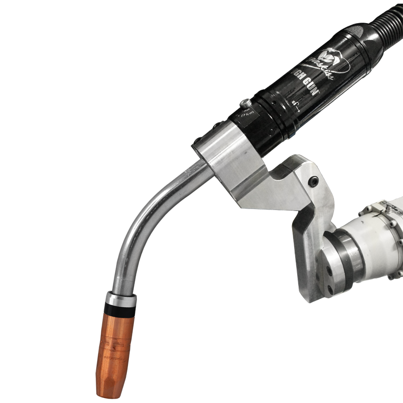
- TOUGH GUN® CA3 robotic air-cooled MIG guns: Featuring a replaceable unicable that offers extended service life to reduce downtime and costs, this gun is a replacement for the TOUGH GUN G1 series MIG gun that maintains TCP with minimal or no robotic programming touch ups. The gun has been engineered for precision, durability, and easy maintenance, and also features an improved neck clamp that resists damage due to accidental over-torque.
- TOUGH GUN TA3 robotic air-cooled MIG guns: A direct replacement for the TOUGH GUN ThruArm™ G1 series MIG guns, these guns feature a re-engineered neck clamp to improve durability and consistency of clamping force on through-arm robotic systems. It is also available with additional standard neck options and includes a low-stress robotic (LSR) unicable that provides a rotating power connection to protect against damage from routine torsion.
WINDSOR, Ontario. July 16, 2015 — As a complement to the already reliable performance of the TOUGH GUN® TT3 reamer, Tregaskiss offers several accessories that are also designed to protect this peripheral. The TOUGH GUN reamer extends the life of robotic MIG guns and consumables by clearing the front end of spatter, helping to enhance productivity and improve weld quality in automated welding operations. Available accessories include: Lubricator: This dedicated motor lubricator is factory-set for optimal pneumatic oil lubrication and is ideal for damp environments. It can be ordered with a new TOUGH GUN TT3 reamer, which extends the Tregaskiss warranty from one year to three years, or retrofitted to an existing reamer. Filter / regulator: The filter cleans the air supply to the reamer, while also restricting debris from reaching the motor, resulting in less contamination and a longer reamer life. The regulator helps ensure the unit receives optimal air pressure. Spray containment unit: To improve air quality and help keep the weld cell cleaner, this unit captures anti-spatter overspray in its sealed basin, channeling it away from the unit to a convenient point of disposal, which can be shared among several Spray Containment units via an optional manifold. TOUGH GUN wire cutter: The wire cutter removes the ball-end of the welding wire to provide smooth arc starts and consistent wire stick-out, and can be used on a variety of wire types up to 1/16 inch in diameter. The wire cutter features a unique carbide cutter blade design with eight indexable cutting surfaces. Replacement cutter blades: These durable and accurate replacement cutting blades for the TOUGH GUN TT3 reamer feature a twin flute design for improved cutting and cleaning performance, all at a competitive price. They are made from harder, stronger material to increase resistance against breaking, snapping, chipping or cracking, and are designed to fit perfectly with TOUGH LOCK® consumables. Tregaskiss v-block: Compatible with Tregaskiss consumables and competitive brands, this four-sided v-block ensures that the cutter is concentric with the consumables and nozzle bore so that the reamer can effectively clear spatter. Tregaskiss offers five available v-block options when users configure a new TOUGH GUN TT3 reamer.
July 8, 2015 Tregaskiss is pleased to announce that the TOUGH GUN® TA3 robotic air-cooled MIG gun offering has been expanded to include configurations for FANUC® M710iC-12L and Kawasaki® BA006N robot models. Click here to learn more about the TOUGH GUN TA3 robotic air-cooled MIG gun.
Selecting equipment to provide the highest quality and productivity in a welding operation goes beyond just the power source or welding gun — consumables play an important role, as well. Contact tips, in particular, can make a significant difference between running an efficient process and accruing downtime to rectify problems. Selecting the right contact tip for the job can also impact the profitability of the welding operation. Contact tips are responsible for transferring the welding current to the wire as it passes through to create the arc. Optimally, the wire should feed through with minimal resistance, while still maintaining electrical contact. For that reason, it is always important to select a high-quality contact tip. While these products may cost slightly more than lesser-grade products, there is long-term value to negate that upfront purchase price. Furthermore, higher-quality contact tips are typically machined to tighter mechanical tolerances, creating a better thermal and electrical connection. They may also feature a smoother center bore, resulting in less friction as the wire feeds through. That means consistent wire feeding with less drag, which eliminates potential quality issues. Higher-quality contact tips can also help minimize burnbacks (the formation of a weld inside the contact tip) and help prevent an erratic arc caused by inconsistent electrical conductivity. They also tend to last longer. Contact tips used for semi-automatic MIG welding are typically composed of copper. This material provides good thermal and electrical conductivity to allow consistent current transfer to the wire, while also being durable enough to withstand the heat generated during the welding process. For robotic welding, some companies choose to use heavier-duty chrome zirconium contact tips, as these are harder than copper ones and better withstand the increased arc-on time of an automated application. In most cases, using a contact tip that matches the size of the wire leads to the best results. However, when wire is fed from a drum (e.g. those 500 pounds and larger) and/or when using solid wire, an undersized contact tip may improve welding performance. Because wire from a drum tends to have less cast, it feeds through the contact tip with less or no contact — having a smaller bore exerts more pressure on the wire, creating greater electric conductivity. Undersizing a contact tip, however, can increase friction, resulting in erratic wire feeding and, potentially, burnback. Conversely, using an oversized tip can decrease current transfer and increase tip temperatures, which can also lead to wire burnback. When in doubt about selecting the proper size contact tip, consult a trusted consumable manufacturer or welding distributor. As a best practice, always check the connection between the contact tip and the gas diffuser to be certain it is secure. Accordingly, a secure connection reduces electrical resistance that could lead to overheating. Contact tip recess refers to the position of the contact tip within the nozzle and is an important factor influencing weld quality, productivity and costs in a welding operation. Specifically, correct contact tip recess can reduce the opportunity for excessive spatter, porosity and burnthrough or warping on thinner materials. It can also help minimize radiant heat that could cause premature contact tip failure. Contact tip recess directly impacts wire stickout, also called electrode extension. The greater the recess, the longer the stickout is and the higher the voltage. Consequently, this makes the arc slightly less stable. For that reason, the best wire stickout is generally the shortest one allowable for the application; it provides a more stable arc and better low-voltage penetration. Typical contact tip positions are 1/4-inch recess, 1/8-inch recess, flush and 1/8-inch extension. Refer to Figure 1 for recommended applications for each. Contact tip failure can result from a number of influences, including burnbacks, mechanical and electrical wear, poor welding operator technique (e.g., variations in gun angle and contact-tip-to-work-distance [CTWD]), and reflective heat from the base material, which is common in tighter access weld joints or confined areas. The quality of the wire being used can also affect contact tip life. Poor quality wire often has an undesirable cast or helix that can cause it to feed erratically. That can prevent the wire and contact tip from connecting properly through the bore, consequently resulting in low conductivity and high electrical resistance. These issues can lead to premature contact tip failure due to overheating, as well as poor arc quality. To extend contact tip life, consider the following: In some instances, it may be desirable to convert to a water-cooled MIG gun to help keep the front-end consumables, including the contact tip, cooler and running for longer. Companies should also consider tracking their contact tip usage, noting excessive changeover and addressing accordingly with some of the suggested precautions. Addressing this downtime sooner than later can go far in helping companies reduce unnecessary costs for inventory, while also improving quality and productivity.
January 16, 2015 Tregaskiss has improved the crimp on our heavy duty (HD) nozzle offering. The profile on the crimping dies that form the ring crimp has been narrowed from a pad length of 0.450″ to a pad length of 0.390″ (see image below). This change significantly improves the quality of the crimp since it allows for enhanced integrity of the nozzle insulator. Click here to download the TOUGH LOCK® consumables spec sheet in PDF format for more detailed nozzle information.
Effective April 30, 2015 Miller Electric Mfg. Co. discontinued the Roughneck® C-Series MIG gun series and replaced them with Bernard® BTB semi-automatic air-cooled MIG guns. Miller Electric will continue to offer consumables and replacement parts for the Roughneck C-Series MIG guns. Please see the cross reference chart below to find the replacement Bernard BTB MIG gun part numbers for the Roughneck C-Series MIG guns: Q3010TE5EMC 12 ft (3.7 m) C-3015 Q3015TE5EMC Q4010TE5EMC C-4012 Q4012TE5EMC 194756 194757 S5010GH5IMC 10 ft (3 m) 194758 C-5012 S5015GH5IMC Certain products are only available for purchase from Miller Electric while others are available from either Miller Electric or Bernard. Please see the reference chart below which indicates where you can place an order for the guns, parts and consumables: PRODUCT WHERE TO BUY FasTip™ Consumables Miller Electric Mfg. Co. Quik Tip™ Consumables Miller Electric Mfg. Co. or Bernard Roughneck® Replacement Parts Miller Electric Mfg. Co. Bernard BTB MIG Guns Miller Electric Mfg. Co. or Bernard Bernard BTB MIG Gun Replacement Parts Miller Electric Mfg. Co. or Bernard To place an order through Miller Customer Service: please contact us via phone: 866-931-9730, fax: 800-637-2315 or email orders@millerwelds.com To place an order through Bernard Customer Service: please contact us via phone: 1-855-MIGWELD (644-9353), fax: 888-946-67-26 or email cs@itwmig.com If you are unable to find the answer you are seeking in the following FAQs, please contact the Miller and Bernard Customer Service Teams. 1. Q: Can I use Miller FasTip™ Consumables on the replacement Bernard BTB MIG Guns? A: Although we recommend the use of Bernard Quik Tip™ Consumables, users can install the FasTip diffuser on Bernard Best of the Best BTB MIG Guns and use FasTip Consumables (contact tips, nozzles). Users will need to order a neck insulator part # 4523R for use on Bernard BTB MIG Guns when using FasTip Consumables. Please use the FasTip consumable chart below as a reference: Contact Tip* M206188 M206190 Diffuser M206195 Nozzle M198855 M199618 Insulator 4523R * Based on wire size range 0.045″ – 1/16″ 2. Q: Can I use Miller Roughneck Liners on Bernard BTB MIG Guns? A: No, Users will need to order Bernard Universal Conventional Liners for Bernard BTB MIG Guns. Miller Roughneck Liners are not compatible on Bernard BTB MIG Guns. 3. Q: Can I use Bernard™ Quik Tip™ Consumables on existing Roughneck MIG Guns? A: Yes, the Quik Tip Consumable Series (contact tip, diffuser, nozzle) can be installed on Miller Roughneck MIG Guns. Users will need to order neck insulator part # 10012 to use on their Roughneck MIG Gun when using Bernard Quik Tip Consumables. Please use the consumable chart below as a reference: Contact Tip* T1045 T1116 Diffuser D118Q D114Q Nozzle N1C58Q N1C34HQ Insulator 10012 *Based on wire size range 0.045″ – 1/16″ 4. Q: Can I use Bernard Universal Conventional Liners on existing Roughneck MIG Guns? A: No, Users will still need to order Miller Roughneck Liners for existing Roughneck MIG Guns. Bernard Universal Conventional Liners are not compatible with existing Roughneck MIG Guns. 5. Q: Why does my Miller FasTip diffuser not thread on correctly to a Bernard BTB MIG Gun? A: A change to the thread on the FasTip diffuser was made on February 13, 2015 to be compatible with Bernard BTB MIG Guns. The new style diffuser has a large Miller logo roll mark compared to the old style diffuser that has a small Miller logo rollmark. To differentiate between the old and new style diffusers please see the comparison images below: 6. Q: How does a Miller Roughneck Gun compare to a Bernard BTB MIG Gun? A: Please see full gun comparison images below of the Roughneck C-Series MIG Gun (bottom) and Bernard BTB MIG Gun (top):
June 23, 2015 This innovative spray containment unit from Tregaskiss helps prevent air contamination by catching anti-spatter overspray in its sealed basin, improving the air quality of the working environment and maintaining the cleanliness of the weld cell. Not sure what type of nozzle you have? Download the Tregaskiss nozzles spec sheet in PDF format. Click here to learn more about the spray containment unit.
WINDSOR, Ontario. June 9, 2015 — Tregaskiss has announced the availability of its new Automation Catalog. Featuring the most up-to-date information on the company’s robotic MIG guns, consumables and peripherals, the catalog has a fresh new look and easy-to-read format. The 22-page, full-color Automation Catalog includes information about the new TOUGH GUN® CA3 and TOUGH GUN TA3 robotic air-cooled MIG guns, including convenient configurator spreads. These pages reflect the online configurators offered by Tregaskiss, which allow users to customize a robotic MIG gun for their exact needs based on amperage, neck and cable styles, power pin, gun mount and more. The catalog also features a new foldout consumables reference chart that provides technical and compatibility information for popular nozzles, retaining heads and contact tips, along with details about TOUGH LOCK® consumables and other Tregaskiss consumable brands. Other new additions to the Automation Catalog include information on:
For some fabricators, the choice between an air-cooled or a water-cooled robotic MIG welding gun is simple. Some heavy-duty applications simply demand a water-cooled model due to the high amperage and duty cycle requirements of the job — performance requirements that would cause an air-cooled gun to quickly overheat and fail. However, there are other less conventional robotic welding applications that may benefit from using a water-cooled MIG gun, too, and can contribute to much lower consumable costs and greater productivity. Water-cooled MIG guns typically have higher duty cycles and amperages, meaning they can be run for longer periods of time without stopping. Cooler guns mean cooler front-end consumables. In particular, it is possible to greatly extend contact tip life with these guns compared to air-cooled models. Deciding which system is the best choice involves careful analysis of several factors. In addition to amperage requirements and duty cycle, a fabricator should consider the up-front costs, potential return on investment (ROI) and the application specifics. Some fabricators may choose water-cooled robotic MIG guns based on the length of welds — the long arc-on time needed to produce these welds generates more heat in the gun. Similarly, critical start and stop points along a longer weld joint typically require a gun that can handle the extended amount of welding. Considering the weld joint design and the material type and thickness, as well as joint access can also factor into whether to choose a water-cooled MIG gun. For example, aluminum or heavy plate sections that have been pre-heated can generate substantial radiant heat that affects the cooling of the gun and can adversely affect the life of the front-end consumables. A water-cooled gun can help here. Some water-cooled robotic MIG guns have smaller diameter necks than air-cooled model due to optimized cooling capacity that requires less copper in the neck. As a result, they can reach into tighter spaces, through complex tooling restraints or into parts with access holes. When deciding whether a water-cooled robotic MIG gun is the best choice, it’s important to keep in mind that these products require more maintenance and often have a higher up-front cost. It is necessary to weigh those factors against the productivity gains and savings that can result from longer consumable life. Keeping MIG welding equipment cool is necessary to protect the power cable, gun body, neck and consumables from damage due to the radiant heat from the arc and the resistive heat from the electrical components in the welding circuit. A traditional water-cooled robotic MIG gun circulates a coolant from a radiator unit through cooling hoses inside the power cable and into the gun body and neck. The coolant returns to the radiator where the radiator’s baffling system releases the heat absorbed by the coolant. There are guns available on the market today, however, that cool only the front of the gun where heat is generated and still use an air-cooled cable. These features help save costs and eliminate potential leaks from the cable bundle where excess movements from whipping and repetitive motion create the greatest wear. These features contrast to a completely air-cooled MIG welding system, which relies solely on the ambient air and shielding gas to dissipate heat that builds up along the length of the welding circuit. Air-cooled systems use much thicker copper cables, and inner neck tubes; water-cooled robotic MIG guns use much less copper in the power cables and thinner wall sections in the necks because the cooling solution carries away the resistive heat before it builds up. In general, water-cooled robotic MIG guns are beneficial for high-amperage applications and are typically available in 300 to 600 amp models. Closely related to amperage is duty cycle, which refers to the amount of time during a 10-minute cycle that the gun can operate at its rated capacity without overheating. Water-cooled robotic MIG guns can have varying duty cycle capacity depending on the manufacturer and model. The amperage requirements, the length of time the arc is actually operating, and how the system will deal with the heat of welding in a specific application are among the most important considerations when choosing a water-cooled robotic MIG gun. When choosing a water-cooled robotic MIG gun, be sure to select a product and consumables that use high quality materials that can handle high heat. Guns on the market come in two styles: conventional and through-arm versions.Through-arm robotic MIG guns carry the cable assembly through the arm of the robot. This style can offer greater protection since the arm of the robot shields the power cable from abrasive wear and minimizes cable whipping during air moves. It’s important to know if the robotic arm is a conventional or through-arm style, so the gun and associated mounting bracket can be chosen to match. Knowing the robot model is also important for proper mounting hardware and insulating of the gun from the robot wrist. As with air-cooled applications, make sure during installation that the selected water-cooled robotic MIG gun allows proper joint access. Having a neck design with the proper geometry that accesses the joint with the appropriate travel and work angles can prevent poor weld quality and/or the need to re-tool expensive fixtures, which could add downtime. To make sure the cable bundle is the correct length, it’s also critical to know where the wire feeder will be located on the robot. If a cable bundle is too short, it might stretch; if it’s too long, it could interfere with opposing structures and also fail prematurely due to excess flexing. Some water-cooled robotic MIG guns on the market have features that make them especially easy to use and to integrate into the robotic welding system. One available feature is the quarter-turn connection, which helps establish a quick and tight connection to help maintain good conductivity and prevent shielding gas leaks. Models with the quarter-turn connection feature are designed to seat the connection properly once a quarter turn is made, making it much easier and faster to change the neck. Water-cooled robotic MIG guns with this quarter-turn connection feature also offer an automatic shutoff valve, to shut off the water flow any time the neck is changed, which helps simplify routine maintenance. Consider adding a flow switch to a system with water-cooled robotic MIG gun. These switches ensure water is flowing through the system; if the system doesn’t detect the flow of water in the gun, it will shut down and give an error message. Operating a gun without water flow will very quickly cause a catastrophic failure. All of this means added downtime and costly repairs. Water-cooled robotic MIG guns do require more maintenance than air-cooled models, since the presence of the water circuit introduces more potential issues. For example, if a hose or the neck is leaking, coolant could drip into the molten weld pool, leading to porosity and costly rework. It’s a good idea to conduct preventive maintenance each day or before the start of each shift. Just as with any welding system, it’s important to inspect a water-cooled robotic MIG gun to ensure that all consumables and connections are tight and working properly. Inspect the water lines frequently to make sure they are tight and have no leaks, and replace the O-rings when necessary (e.g., when cracks or wear appears). Using an automatic reamer or nozzle cleaning station adds significant benefits to the preventive maintenance of water-cooled robotic MIG guns. A reamer eliminates the need to manually clean out the front-end consumables and can, with the addition of an automated sprayer, add anti-spatter compound to help extend consumable life further. This feature adds to the overall cost of the equipment, but helps increase uptime for production, with less manual intervention, and offers a solid return on investment in most robotic welding operations. Do not fall prey to the notion that it is cheaper to use tap water in a water-cooled gun, as it can cause algae growth or mineral build-up and eventually clogging. Instead, use deionized water or the specially treated coolant solution recommended by the manufacturer. These coolants contain special additives to lubricate internal pumps and O-rings, as well as to prevent algae growth. Choosing a water-cooled robotic MIG gun is often a necessity because of the demands of the application. A water-cooled model requires more up-front investment and more maintenance, but it can provide significantly longer consumable life and increased productivity from fewer consumable changeovers. Consider the various costs, specific application needs and accessibility to decide if a water-cooled robotic MIG gun offers a good option for a specific robotic application. Often a welding distributor, welding equipment manufacturer or robotic welding system integrator can help. WINDSOR, Ontario. May 4, 2015 — A Tregaskiss-sponsored robotics team from Vincent Massey Secondary School of Windsor, Ontario, Canada, attended the FIRST Robotics World Championship in St. Louis on April 22 — a first-time appearance for the students at a world-level competition. The team, which consisted of 40 students in grades 9 to 12, competed against the world’s best robotics teams, placing 44th out of 77 in their division (there were 600 teams total), and gaining valuable experience to take into competitions in 2016. Over 40,000 spectators attended the event. “The trip was such a positive experience for the students and the teachers/mentors, and we appreciate all the support we received along the way,” said Sandra Chappus, robotics team mentor. “The students and the robot performed at their personal bests, so everyone is quite pleased. We’re already looking to learn new technologies to take into competition next year.” Among those new technologies is pneumatics, a feature that a top-ranked team at the competition sought the Vincent Massey teams help with during the competition. Currently, the team is focused on mechanical, electrical, business/media and programming facets. According to Tregaskiss Director of Operations Darren Grey, the company plans to continue its sponsorship of Windsor-area robotics teams in the future, and many employees have expressed an interest in mentoring students as they prepare their robots for competition next year. “We consider programs like these to be an important investment in the students’ futures,” Grey said. “Tregaskiss is a natural fit to support automation technology and we are proud to be able to help.”
WINDSOR, Ontario. April 16, 2015 — Tregaskiss recently partnered with Vincent Massey Secondary School of Windsor, Ontario, Canada to sponsor their robotics team for the Windsor-Essex Great Lakes Regional FIRST Robotics tournament on April 2-3. The event featured 48 teams totaling more than 1,000 students. The Vincent Massey Robotics Team qualified for the finals, advancing the 40 students on the team (grades 9 to 12) to the FIRST Robotics World Championship in St. Louis on April 22, where Tregaskiss will also offer its sponsorship support. “Our students are thrilled to have a chance to compete at such a high level after only the second year as a team,” says Sandra Chappus, mentor for the Vincent Massey Robotics Team. “The students’ talent is definitely matched by their enthusiasm and they have exceeded their own expectations going into the FIRST event. We are thankful to all of our sponsors, including Tregaskiss, for their help. Without that support, the students wouldn’t have such great opportunities.” “The FIRST Robotics competition allows students to immerse themselves in an initiative that mirrors industry in the real world,” adds Darren Grey, director of operations at Tregaskiss. “Within a short timeframe and with a limited budget, they are tasked with designing and manufacturing a working robot to compete against teams from across the US and Canada. We consider our sponsorship an important investment in these students’ futures — they are aspiring to be the engineers, technologists and scientists of tomorrow.” The Windsor-Essex Great Lakes Regional FIRST Robotics tournament consisted of robots competing to stack totes and recycling bins and maneuver pool noodles. Students spent six weeks building their robot and coding it for the task. The team is broken into four divisions — mechanical, electrical, business/media and programming — allowing students to focus their strengths on executing the task.
Manufacturing and fabrication environments are dynamic, ever changing with the economy, customer demands, available labor and skill sets, and competitive forces, among other factors. To maintain a favorable position in the industry, it is critical for companies to continually look for ways to increase efficiencies while also improving quality and decreasing costs. For many, that means a shift toward welding automation, which has experienced its own changes in the last 10 years. During this time, robotic welding manufacturers have transitioned away from the manufacture of conventional robotic welding systems to the development of through-arm styles, in which the power cable of the robotic MIG gun runs through the arm of the robot as opposed to over top of it. These are now the prevalent robot styles in the industry and this change has had a direct impact on the design of the robotic MIG guns for the marketplace. But it is not the only trend associated with robotic MIG guns. Like any component of the welding operation, this equipment has continued to evolve to the demands of the industry and to provide solutions to improve the business of welding. Improving and simplifying cable management has been the driving force behind the shift toward through-arm robots and, therefore, the development of through-arm robotic MIG guns to accompany them. With conventional style robots and guns, the cable is prone to “whipping” during air movements, which causes undue stress on this portion of the gun, and can lead to premature wear and failure caused by the cable rubbing against the robot or tooling. It also creates additional cost and time for companies to implement cable management systems. The through-arm style robot and through-arm robotic MIG gun make it easier for companies to minimize downtime associated with cable management and reduce costs for cable replacement. It also eliminates the risk of selecting the wrong cable length, a common mistake that occurs with conventional robotic MIG guns. The through-arm robot model dictates the length of the robotic MIG gun cable, so there is no concern about it being too long (which requires extra cable management or could cause wire feeding issues) or being too short (which can cause the cable to stretch and fail prematurely) — both issues associated with conventional robotic MIG guns. There are other benefits to the shift to through-arm robots and through-arm robotic MIG guns, namely that they can accommodate for increases in welding speed that are also becoming customary in the industry. Robots are getting much faster, but with the through-arm robot there is no longer the concern of the robotic MIG gun cable getting caught on tooling during quick movements. Too, it is easier to complete offline robot programming or welding simulation and have it work with these robots because there is less concern about having to accommodate for clearance for the power cable in an application. If a robotic MIG gun fitted for a through-arm robot works in simulation, it will most likely work in the real-world application. As companies strive for greater arc-on time and higher productivity, robotic MIG gun manufacturers are helping by providing increasingly more durable power cables on this equipment and implementing features that simplify cable changeover. Some manufacturers offer a rotating power connection on the front of the cable that allows the robot to spin on its final axis as much as necessary without binding the cable. This feature helps minimize stress due to routine torsion and to extend the life of this part of the gun, as well as to increase the robot’s operating range by allowing it to rotate a full 720 degrees (360 degrees in both directions) and weld faster. Built-in quick-change features on many robotic MIG guns also expedite cable replacement, adding to the operation’s productivity, while the use of stronger cable materials help better resist wear and UV damage from the arc for longer component life. Another trend associated with robotic MIG guns is the use of solid mounts (also called solid arm mounts) as opposed to the clutch mounts that were used previously to protect the gun in the event of a collision — an occurrence commonly caused by an incorrectly position work piece or tooling that has been left out of position, among other factors. This trend is due to more sophisticated collision detection software being built into today’s robots. This software is increasingly capable of monitoring current rates and/or torque so it can quickly stop the robot when an impact occurs. Solid mounts are made from durable, high-strength aluminum alloys, and are an alternative to the clutches used with older robot models. There are two key benefits to using a solid mount for robotic MIG guns compared to a clutch: Clutches (also called shock sensors) are designed to recognize the physical impact of the robotic MIG gun on a solid surface during a collision and send an electrical signal back to the robot controller, causing the system to stop. While effective, clutches are designed to move, which can affect tool center point (TCP) after a collision. Also, since it is an electrical device, it costs more than a solid mount and is more prone to failure because of its internal components — expenses that many companies can now happily omit. As companies seek ways to become more competitive and produce higher volumes of parts, they need to maximize floor space to make room for more robots to do the job. As a result, robots and welding cells are becoming smaller and in many instances, tooling has become more complex. These changes pose greater space constraints when it comes to the robotic MIG gun. Many robotic MIG gun manufacturers have responded to this trend by creating guns that provide a more open work envelope around the mounting arm (the depth from the wrist of the robot to the tip of the robotic MIG gun) so maneuvering around tooling and gaining joint access becomes less cumbersome. There are also more options for neck lengths and angles available for robotic MIG guns, which helps companies gain access to complicated joints. Because many robotic welding applications tend toward higher amperages and longer arc-on times, it is critical for companies to have a robotic MIG gun that provides adequate amperage without overheating. The complexity and increased cost of water-cooled robotic MIG gun systems (compared to air-cooled models), however, make some companies wary of the investment for their high amperage applications. Too, if there is an issue with the coolant flow, there is the risk of the robotic MIG gun overheating and failing — an event that can be costly not just for replacement of the gun, but also potentially for rework of the part should quality problems occur. A development in recent years that addresses this concern is a hybrid robotic MIG gun. This type of gun has a durable neck like an air-cooled model and water lines that run external to the neck down to the nozzle. Should the coolant flow fail, the gun can rely on the underlying air-cooled unicable to provide enough current-carrying capacity for the job for a period of time, saving downtime and costs to address a complete robotic MIG gun failure. These guns also offer the higher amperage associated with a standard water-cooled gun, making them a good option for companies who need greater cooling capacity for an application. Because time is at a premium when it comes to robotic welding, companies are always looking for ways to extend their robotic welding cycle time — down to the second. To help maintain greater arc-on time while still protecting the robotic MIG gun and consumables from spatter build-up that could affect weld quality, adding air blast to robotic MIG guns is becoming a popular choice with some companies. This optional feature can be added to the robotic MIG gun and functions by blowing compressed air through the gun at a high pressure (approximately 100 pounds per square inch — psi) to clear debris loose in the front end while the robot is moving out of the way so the table/fixture can index. This addition can help companies reduce the number of times that the robotic MIG gun needs to be reamed out by a reamer or nozzle cleaning station, resulting in more arc-on time and greater productivity. While robotic MIG guns may seem like a small part of the whole automated system, their design and functionality can have a significant impact on the cost, productivity and quality of an application. The trends discussed here are just some of the ways that robotic MIG gun manufacturers have adjusted the designs and capacity of the products to help companies gain the best results in recent years. As with any piece of welding equipment, robotic MIG guns will need to continue evolving just like any equipment in order to meet companies’ changing needs and to meet the demands of the fabrication and manufacturing industry.
Consider some of the top things to know about robotic MIG guns as a way to get the most out of this equipment. When it comes to robotic welding, precision, repeatability and speed are essential to ensuring a successful outcome in the operation. In order to gain the best benefits, companies rely on the robot’s ability to execute the same weld, exactly the same way and as fast as possible. And while the robot itself, proper programming and oversight by a trained welding supervisor are all important components in the robotic welding operation, the robotic MIG gun also has a direct impact on quality and productivity, as well as costs.
Equipment repairs are a fact of life on most jobsites, so finding ways to reduce costs and downtime while making them is important for overall efficiency and productivity — and the bottom line. The welding operation on a jobsite, just like any other portion of the business, offers opportunities to conserve resources and extend equipment life. Proper selection, handling and use of welding consumables and accessories can be helpful when it comes to getting the most out of a MIG gun, as can proper gun maintenance. Jobsites are often exposed to many environmental challenges, including extreme hot and cold temperatures, and the presence of rain and mud. It’s important to keep nozzles, gas diffusers and contact tips in the original packaging to protect against these elements until they are ready for use. Doing so also prevents scratches and/or dents from forming where spatter can accumulate and cause the consumables to fail prematurely. In addition, it prevents dirt, oil or other debris from adhering to the consumables and inadvertently entering the weld puddle, which can lead to poor weld quality. Remember, proper storage and handling doesn’t just lower actual costs for consumables by extending consumable life, it can also prevent weld defects that require costly and time-consuming rework. Choose the most appropriate neck for a MIG welding application in order to increase comfort and control, and save money. Rotatable necks, for example, can be adjusted without tools, so neck angles can be quickly changed during a welding repair once the desired position is determined. This feature is important on a jobsite where welding may be done in various positions or in tight spaces, and it helps reduce downtime for changing over MIG guns or for purchasing and inventorying extras. Rotatable necks are especially useful for welding on different angles. For hard-to-reach areas, consider a neck coupler, which allows for two existing necks to connect to extend their reach — again without the cost of purchasing a new or specialized neck. Flex necks are another good option for saving money and gaining greater comfort and control, particularly for applications with tighter joints. The operator can bend the neck to multiple angles to work around corners or get into small spaces for greater flexibility during repairs, without the expense of stocking different neck angles. Regularly perform a visual inspection of the nozzle — inside and outside — to look for spatter build-up. If there is accumulation, either clean the nozzle with a tool designed specifically for the job or replace the nozzle when necessary. During the inspection, also check that the nozzle, contact tip and retaining head are tightened properly, as these components can naturally loosen during welding. Inspecting and tightening consumables help ensure good shielding gas coverage, reliable electrical conductivity and consistent weld quality, as well as reduce costs for purchasing and replacing new consumables. It is also important to inspect the power cable on the MIG gun for any wear or damage, replacing it as necessary to avoid potential problems. Always trim MIG gun liners according to the manufacturer’s recommendations, using the proper tools and cutting the liner to the correct length. Too long of a liner can cause kinking, while cutting it too short allows debris to build up between the liner and the gas diffuser. Either way, the wrong liner length can cause poor wire feeding and premature failure of both the liner and the contact tip, adding unnecessary costs. Use a liner gauge when possible to determine the proper length for the particular liner being used. Also be certain that there are no burrs or sharp edges after the liner is cut. Also, keep the liner away from contaminants (e.g., don’t let it drag on the ground) during installation. As further protection, the welding operator’s hands or gloves should be clean when handling the liner. These precautions protect against contaminants that could enter the weld puddle and cause costly weld quality issues or downtime for rework. Use the shortest length MIG gun cable possible for the welding application, as it minimizes the opportunity for kinking, as well as premature wear of both the cable and the MIG gun liner. A shorter cable also helps prevent wire-feeding problems that could lead to an erratic arc, poor weld quality and unnecessary downtime for rework or consumable replacement. It also tends to cost less, adding to savings for repair jobs. In addition, remember to choose the correct diameter liner and contact tip for the welding wire, as this prevents similar problems and helps extend the life of these consumables. While up-front cost is an important factor when choosing consumables, consider the long-term savings offered by purchasing sturdier and more expensive consumables. These consumables likely will last longer — especially in the face of the harsh conditions of some jobsites — reducing the downtime associated with changeover and the cost of more frequent replacement of the consumables themselves. As an additional defense against spatter accumulation, purchase nozzles that have a smooth, non-porous surface. Be sure to check that the nozzles are free of any sharp edges or flat spots that would further allow spatter to adhere. Whenever possible, purchase MIG guns and consumables that are backed by a reliable manufacturer’s warranty, and use all guns and consumables as intended so as not to void the terms and conditions. Keeping these simple tips in mind can help reduce the downtime spent on maintenance and MIG gun or consumable changeover, so welding operators can get back to welding faster, get equipment back into service sooner and save money.
When it comes to welding, no two applications are alike. Just as it’s important to select a power source that is right for the job, it is also essential to select a MIG gun that will deliver the appropriate amperage and cooling capabilities. There are four main MIG gun categories to consider when making the selection: light-duty, heavy-duty, air-cooled and water-cooled. Like any welding equipment, each has its advantages and disadvantages, as well as applications for which it is best suited. Depending on the amount of arc-on time required for an application and the amperage needed, a light- or heavy-duty MIG gun may be the best choice. The key is to make sure that the gun provides the necessary amperage to avoid overheating and premature failure. As a general rule, light-duty MIG guns work well for welding on thin materials, like sheet metal, for tacking or for other applications that require short arc-on times. These guns tend to be smaller and lighter than heavy-duty guns, making them more comfortable for the welding operator, and most MIG gun manufacturers offer them in models ranging from 100 to 300 amps. Light-duty MIG guns also tend to be less expensive than heavy-duty ones and use light- or standard-duty consumables (nozzles, contact tips and gas diffusers) that are also less expensive. There are some limitations to consider when using light-duty MIG guns, too. Despite the lower purchase price, these guns may need to be replaced more frequently due to the lighter-duty components. For example, the strain relief on light-duty guns is often made from a flexible rubber component or absent all together, which can sometimes lead to kinking and cause poor wire feeding and/or shielding gas flow. Also, some unicables on light-duty MIG guns have crimped connections and may not be able to be repaired, requiring replacement of the cable or possibly the entire gun. Heavy-duty MIG guns are typically the best option for applications requiring multiple passes on thick sections of material or for long durations of welding. They are available in the marketplace in both air- and water-cooled models (discussed below) ranging from 400 to 600 amps. The necks on these guns are often longer, which creates more distance between the welding operator and the high heat from the arc, and the handles on these guns are usually larger, too. While the handle size is vital to accommodate the larger cables necessary for higher amperage output, it can make the gun more cumbersome for the welding operator to maneuver. These guns frequently also use heavy-duty front-end consumables that are capable of withstanding high amperages and longer arc-on times, but they are more expensive. Choosing between a water- or air-cooled model for high-amperage, heavier-duty applications depends on several factors, including the amperage required, cost and operator preference. As with the considerations for a light-duty gun, applications that involve welding at lower amperages for less amount of time are best suited to air-cooled MIG guns. These guns rely on the ambient air and shielding gas to dissipate the heat that builds up along the length of the welding circuit. These systems, which range from 150 to 600 amps, use much thicker copper cabling than water-cooled systems so the guns are generally larger. Water-cooled MIG guns are best suited for applications that require long, continuous welds and are typically available in a range from 300 to 600 amps. These guns operate via a water-cooled MIG welding system that pumps cooling solution from a radiator unit, usually integrated inside or near the power source. This coolant passes through hoses inside the cable bundle and into the gun handle and neck. The coolant returns to the radiator where a baffling system releases the heat absorbed by the coolant. The ambient air and shielding gas further disperses the heat from the welding arc. Each MIG gun has its advantages and disadvantages. Water-cooled MIG guns are more expensive up-front and can require more maintenance and operational costs. However, water-cooled guns also are much smaller and lighter than air-cooled guns, so they can provide productivity advantages by reducing welding operator fatigue. Also, because water-cooled guns require more equipment, they can be impractical for applications that require portability. The goal when selecting between air- or water-cooled guns, as well as light- or heavy-duty models, is to weigh out pros and cons like these and always make the selection that will provide the capacity to prevent downtime and drive productivity. Premature contact tip failure is a common problem that can lead to unexpected downtime — and added costs — in a welding operation. This issue not only hinders productivity, it can also negatively affect weld quality and create rework. Contact tips play a critical part in achieving high quality welds. Because of the constant friction from the wire and the exposure to the heat of the arc (and, in some cases, the reflective heat from the base material), contact tips take a tremendous amount of abuse during welding. This can easily turn into premature contact tip failure without the proper precautions. Understanding the typical types of contact tip failures and their causes is the best approach to preventing them. There are two main types of contact tip failure. 1. Failure that leads to a burnback and its associated problems 2. Failure that produces contact tip wear Burnbacks occur when a weld forms within the contact tip and can occur at any point along the weld. They are not necessarily the result of poor contact tip performance, but rather burnbacks can result from too slow of wire feed speeds and/or incorrect contact-tip-to-work distance (also referred to as CTWD). The CTWD is the distance between the end of the contact tip and the base material; if the distance is too short (i.e. the contact tip is too close to the workpiece), a burnback can occur. The quality of the wire, incorrect parameter settings and micro-spatter buildup, as well as incorrect wire feeder and liner adjustments can all contribute to burnbacks. When they occur, burnbacks reveal themselves by way of poor arc starts, arc instability, inconsistent wire feeding and, ultimately, stoppages in wire feeding altogether. Contact tip wear can be both mechanical and electrical. It occurs from the friction of the wire feeding through the bore of the contact tip and is especially prevalent in higher amperage semi-automatic and robotic applications. In the latter, contact tip wear can produce issues with tool center point (TCP), resulting in offset welds and potentially rework, especially in robotic welding systems that do not employ seam tracking. The design of the contact tip and the material it is composed of are two factors that affect a contact tip’s tendency toward wear. Typically, manufacturers use copper for contact tips because it is readily available and offers good electrical and thermal conductivity. Copper, however, has a relatively low resistance to wear, making it more prone to failures. For higher amperage applications, companies often turn to chrome zirconium contact tips due to their strength and their ability to resist wear by heat. All contact tips, regardless of the material used to manufacture them, will eventually fail if used or abused for a long enough periods of time and/or at a high enough temperature. They are, after all, consumables with a finite lifespan. The goal, nonetheless, is to prolong the life of the consumables in order to avoid unnecessary downtime, as well as cost for additional inventory. A good step in achieving those goals is to understand the ways to help prevent contact tip failure. Burnbacks: There is no one solution to minimize contact tip failure due to burnbacks; each situation is unique and may require a series of corrective actions. The goal is to address the associated errors or issues that are leading to the burnback in the first place. The two key solutions for minimizing burnbacks include increasing the wire feed speed and/or lengthening the distance of the MIG gun from the workpiece. The nozzle should be no further than one-half inch from the base metal. Matching a welding wire with the appropriate cast for the contact tip bore tolerance can also reduce the risk for burnbacks, as it helps improve electrical contact and reduce CTWD variability. The wire’s cast is affected by three main factors: the supply reel (spool or drum); drive roll tension; and MIG gun neck angle. A tight wire cast may allow for a looser bore tolerances and still be able to make the appropriate electrical contact with the contact tip to create a stable arc. A straighter cast may require a contact tip with a tighter bore to exert pressure on the wire and create consistent conductivity. It is important to note that with a smaller contact tip bore, there is a risk of the spatter build up, so cleanliness is key. Selecting contact tips with a smooth surface and bore can also help prevent the wire from snagging on the consumable and causing a burnback. Using a contact tip/gas diffuser design that maximizes the surface area between these consumables is another option to reduce the potential for this problem — the tight connection creates less heat and can reduce micro-spatter that could hinder the wire from feeding and becoming blocked in the contact tip bore. Additional preventive measures include: • Adjusting the drive rolls to ensure smooth wire feeding Contact tip wear: The degree of wear on a contact tip depends on multiple factors, including operating temperatures; the wire cast; and the surface condition, material properties and bore tolerances of the contact tip. Lowering operating temperatures, when feasible, is among the best defenses against contact tip wear. These lower temperatures can be achieved in a number of ways, for example, using a water-cooled MIG gun. These types of guns are especially well suited for higher amperage applications (usually between 300- and 600-amps). They do, however, introduce some additional complexities to the welding operation that companies need to consider. Namely, water-cooled guns have a weaker neck than air-cooled models, so in robotic applications specifically, they can be more prone to bending in the event of a crash. They also tend to be more expensive to maintain. When deciding whether to use a water-cooled MIG gun to help combat the excessive heat that could lead to contact tip wear, users will have to weigh out the advantages and disadvantages of this equipment in terms of costs and productivity to determine if the product is the best choice. An alternative to reduce contact tip wear via lower temperatures would be to use a thermally-effective air-cooled torch in combination with front end consumables designed to dissipate heat. Typically, high quality consumables have been designed to seat firmly together to minimize electrical resistance, thereby generating less heat and reducing the opportunity for contact tip wear and failure. Remember that cheaper isn’t always better. When it comes to purchasing consumables, it may be worth the extra cost upfront for such a design in order to minimize long-term costs and downtime associated with contact tip changeover. In any welding operation, there is no single solution to instill efficiencies — it can be a matter of technique, equipment and more. However, minimizing contact tip failure is an important way to reduce downtime and costs, while also ensuring higher weld quality. Be sure to train new welding operators as to the value of taking preventive measures to combat burnbacks and contact tip wear, emphasizing the impact of these occurrences on the overall welding operation. As with any process, education can go a long way in helping companies create a more productive and profitable business.
Outdoor jobsites can be harsh environments for welding equipment, including guns and consumables. When it comes to MIG or flux-cored (FCAW) welding on the jobsite, selecting the right gun for the application, and following some basic maintenance and preparation tips can help make guns and consumables last longer — factors that can help reduce costs, increase productivity and improve weld quality. Keeping this equipment up and running also helps minimize unscheduled downtime, which is key to meeting contract deadlines and keeping the business moving. This article discusses tips for protecting and maintaining MIG guns and consumables on the jobsite. Welding guns often take a lot of abuse on jobsites and in job shops, so it’s important to look for a durable gun that meets the demands of a specific application. Variables to keep in mind when selecting the gun include the material type and thickness to be welded, and how much welding will be required (if welding makes up one hour versus seven hours of each workday, for example). Additional challenges on outdoor jobsites are the weather and wind, which can blow the shielding gas away from the weld puddle, causing porosity in the completed weld. For this reason, a popular option for many outside contractors is a flux-cored welding gun, which can be used with self-shielded wire that generates its own shielding gas to reduce problems caused by wind. Whether using a MIG gun or a flux-cored gun, it’s important to select a gun with a rigid strain relief. A good strain relief (which refers to the connection between the power cable and power pin) helps minimize kinking, which can lead to poor wire feeding, an unstable arc and poor weld quality. • The gun should have enough amperage to meet the needs of the application. To determine the necessary amperage, consider the material type and thickness and wire size being used. • The power cable must have enough copper content to handle the amperage that will be put through it. When possible, use shorter power cables on the MIG gun to minimize costs and downtime further. As a general rule, shorter power cables are less expensive and offer better maneuverability. Shorter power cables also can help minimize wire-feeding problems associated with kinking and coiling. • The handle of the gun often is what takes the most abuse, so make sure to select a handle durable enough for the application, as some handles are designed for more light-duty applications. Choosing a handle that is comfortable for the welding operator also is important, so consider using the smallest handle that can still meet amperage needs to help minimize fatigue. • MIG gun triggers come in various styles and designs, such as standard, locking and dual schedule, and selecting the trigger often comes down to operator preference. Select a trigger that’s comfortable to use and easy to access for servicing. Some applications may be well suited for a dual-pull trigger, which allows the operator to easily switch between settings without stopping and walking back to the power source to make changes. Reducing those trips to the power source also helps improve safety by eliminating the need to navigate through cluttered jobsites and with it the potential for slips or falls. Regularly inspecting the MIG gun can be an important part of reducing costs and ensuring good welding performance, impacting productivity and efficiency. Preventive maintenance for MIG guns and flux-cored guns doesn’t have to be time-consuming or difficult. Often, the fundamental principles are the same, whether the welding is being done on a jobsite outside or in a shop. Here are some key tips for maintaining a welding gun on the jobsite: • Make sure all connections are tight. Inspect the connections between the contact tip, gas diffuser, nozzle and power pin. The wire feeder connection (where the power pin plugs into the feeder) must be tightened properly and should be free of dirt and debris. Loose or dirty wire feeder connections can cause heat to build up, leading to voltage drops that adversely affect the welding arc and may cause premature gun failure. Tighten the connection according to the manufacturer’s specification or replace the direct plug if necessary to obtain a secure fit. • Properly care for the gun liner. Make sure to install only a clean gun liner. Dragging a liner through the dirt while installing it can allow dirt and debris to accumulate on it, causing wire feeding issues. Having the proper cut length on the liner is also extremely important to help prevent birdnesting. It’s not uncommon during the course of welding for the gun liner to become clogged with debris. This accumulation of debris can, over time, lead to poor wire feeding, bird-nesting and burnbacks that require downtime to fix. Spraying compressed air through the liner can help clear out potential blockages. • Visually inspect the power cable. Look for any damage such as nicks or cuts in the power cable, which can affect wire feeding or conductivity. Power cable maintenance is an important part of eliminating unnecessary equipment costs and improving jobsite safety. Cuts in the cable can expose copper wire and lead to a potential shock hazard, while kinking obstructs gas flow and wire feeding, which can result in weld defects and arc instability. • Inspect the handle and trigger. Typically these components require little maintenance beyond visual inspection, but be sure to regularly look for cracks on the handle or missing screws. Check that the gun trigger is not sticking or otherwise malfunctioning, and replace these components as necessary. • Check the gun neck. Loose connections at either end of the neck can cause electrical resistance that leads to poor weld quality and/or consumable failures. Also, visually inspect the insulators on the neck and replace them if damaged. These insulators prevent electrically live components from exposure, ensuring operator safety and longevity of equipment. • Be mindful of consumables. Frequently inspect the nozzle and contact tip for spatter build-up, which can obstruct shielding gas flow and cause weld defects that will need to be reworked, costing time and money. Spatter build-up also can cause consumables to fail prematurely. Replace the nozzle and contact tip when necessary. • Store the gun and consumables properly. Welding equipment performs best when it’s properly stored, such as in a box or cabinet, and kept out of the elements. Liners can become corroded from exposure to the environment, which impacts the conductivity and performance of the gun. Regular and basic care and maintenance can help extend welding equipment life on a jobsite. Simple steps such as ensuring all connections are tight and in good working order and that the weld ground is good can help produce results every day. Inspection of the MIG or flux-cored gun, equipment and consumables every time the machine is started can keep things running smoothly and reduce unplanned downtime, which helps reduce costs, extend consumable life and improve welding performance.
December 31, 2014 The TOUGH GARD® spatter cleaner has been discontinued as of December 31, 2014. Replacement parts will continue to be available until December 31, 2015. Prices and availability of these replacement parts are subject to change without notice. Consider an upgrade to the TOUGH GUN® TT3 (analog) or TT3E (Ethernet) reamer robotic nozzle cleaning station from Tregaskiss. Click here to learn more. Click here to download the M075 TOUGH GARD spatter cleaner technical guide.
Estimated reading time: 11 minutes The cost to implement welding automation can be substantial, requiring companies to plan out the purchase carefully and to justify the expenditure to the appropriate financial or management personnel. The payback on the investment, however, can be equally beneficial. From productivity increases to quality improvements and cost savings, companies can often position themselves for greater competitiveness in the marketplace by adding robotic welding systems to their welding operation or by replacing manual welding cells altogether. Unlike companies that employ semi-automatic welding, those with robotic welding systems have the added responsibility of protecting the large capital investment in the equipment. But no two robotic welding systems are the same and likewise, there is no single step to ensure a successful outcome. Rather, a combination of the appropriate planning, equipment purchases and personnel training — among many other things — provides the best results. Paying close attention to the daily occurrences in a robotic welding cell and engaging regularly in some of the best practices discussed here can also help provide high quality results. Companies typically invest in welding automation to expedite the welding process, gain more consistent weld quality and/or to reduce costs. The process can also set companies apart from the competition by allowing for faster completion and delivery of products. For companies with high-volume demands and low-variation parts, robotic welding can become an important part of their production plans. Smaller companies with lower-volume, high-variety parts can also benefit, but they may require more flexible tooling and more programming time to accommodate for several types of products. The important consideration for both high- and low-volume production is to ensure that the parts to be welded lend themselves appropriately to an automated welding process. Robotic welding systems rely on consistent parts to provide consistent results. Companies that have or are planning to implement a robotic welding system need to be certain that parts are simple and repeatable. The presence of gaps, poor fit-up or poor joint access can have a detrimental impact on the high quality sought with robotic welding systems. Similar to a semi-automatic welding application, consistent workflow is also important for a successful robotic welding operation, with the main difference being the speed at which parts are delivered and welded since a robotic system is so much faster. The parts need to enter and leave the cell at a quicker and steadier rate — without bottlenecks — to gain optimal throughput. Companies should assess each activity leading up to the part entering the cell, making sure that the supply of parts matches the robot’s cycle time, and also assess the steps for handling the part after it leaves. In some cases, it may be necessary to change how the parts are fabricated upstream and completed downstream (e.g., finishing, painting, etc.) to establish good workflow. Companies should also look to eliminate non-value added activities, including excessive lifting or handling of parts, and avoid multiple trips to stack products or other similar activities. Robotic welding systems typically operate at higher amperages and longer duty cycles than semi-automatic welding operations — the robots can withstand the greater arc-on time and heat compared to a human operator. While those increases are excellent for supporting high productivity, the additional heat and welding duration can be especially harsh on consumables — nozzles, contact tips and gas diffusers (or retaining heads). Companies need to take steps to avoid the pitfall of excessive consumable changeover. Entering the weld cell for purposes other than part changeover or routine pauses in the operation can add unnecessarily to downtime, which can easily add up per shift, day, month and year, resulting in lost productivity. Excessive consumable changeover is also costly, as it increases inventory and inventory management. There are two key steps companies can take steps to increase consumable life in their robotic applications and reduce downtime. One, install consumables properly and maintain tight connections throughout the course of welding. Loose connections increase electrical resistance, causing the consumables to generate additional heat that can shorten their lifespan and/or cause them to perform poorly. Follow the manufacturer’s instructions for proper consumable installation, taking care to tighten the consumables appropriately. It’s also a good idea to check the consumables periodically during routine pauses in welding, as they can loosen throughout a shift. Two, install the robotic MIG gun liner properly, as this helps prevent downtime to address wire feeding issues or to correct a burnback, in which the wire “burns back” into the contact tip. Follow the manufacturer’s instructions for trimming and installation, using a liner gauge to confirm the correct liner length. Preventing premature power cable failure, which can occur in both through-arm robotic welding systems (where the cable feeds through the arm of the robot) or in standard robotic welding systems (also referred to as over-the-arm) is also important. Be mindful of the path the robot has been programmed to follow, the speed at which it moves and the cable length. The power cable should clear the robotic arm and tooling to prevent it from catching or rubbing against either part. Also, the robot should be programmed not to move too fast or abruptly. Aggressive movements can cause the power cable to snap. Make sure that the cable is the appropriate length — too short of a cable can stretch beyond its capacity during routine robotic movements, leading to greater wear. If the power cable is too long, it may be prone to kinking or becoming pinched by the robot’s arm. Preventive maintenance (PM) programs are among the most effective best practices a company can instill for a robotic welding system. Ideally, PM programs should cover every aspect of the system — from the robot to the contact tip. Proper PM activities can help prevent unscheduled downtime, low quality parts, costly repairs and/or equipment replacements. Companies will need to assess their PM needs on an individual basis and engage a maintenance team or other personnel to carry out the activities at the appropriate times and intervals. As a general rule, companies that weld thick materials or have applications with long, continuous welds common in welding automation can benefit from more frequent PM activities, as the rework for quality issues can generate much more costly rework compared to an application producing multiple smaller parts. Several PM activities can occur during routine pauses in production, including: • Cleaning the robot and fixturing to prevent the buildup of dirt, debris or anti-spatter compound, which could affect part fit-up. Other activities that happen less frequently like greasing the robots joints can be completed during a longer scheduled stop. Peripherals are often an overlooked part of the robotic welding system. The added cost of this equipment, which includes nozzle cleaning stations (also called reamers or spatter cleaners), is frequently considered an unnecessary expense. In reality, this equipment can maximize robotic welding performance and help companies gain a better return on investment (ROI) from their robotic welding system. As its name suggests, a nozzle cleaning station cleans the nozzle of dirt, debris and spatter, typically during routine pauses in the robotic welding operation. The goal of this cleaning action is to help ensure consistent shielding gas coverage, and with it, reduce weld defects, expensive rework and lost productivity. A nozzle cleaning station also helps extend the life of consumables, minimizing the downtime and expense for changeover. For the best results, the nozzle cleaning station should be mounted in close proximity to the robot to reduce the amount of time necessary for its arm to reach it. Companies can mount the peripheral overhead if need be. The robot should be programmed to clamp onto the nozzle cleaning station at a taught position exactly perpendicular to the cutting blade that clears out the spatter or other debris. Any misalignment to the position of the nozzle could lead to partial cleaning of the nozzle and excessive spatter build-up. Program the robot to go to the nozzle cleaning station as often as possible; the cleaner the consumables are, generally the better performing and longer lasting they will be. For companies who choose to attach an anti-spatter sprayer, it’s important to locate the spray in the appropriate position so it completely coats the inside of the nozzle. Ideally the outside should be covered to within three-quarters of an inch from the bottom of the nozzle. Other peripherals that companies can integrate into their robotic welding system include a wire cutter and a neck inspection tool (discussed in the next section). A wire cutter cuts the welding wire to a specified length, removing any inconsistencies at the end, providing for more reliable and smoother arc starts and better seam tracking for robots featuring that technology. For companies using touch sensing software, using a wire cutter in conjunction with a robotic MIG gun featuring a wire brake can help prevent problems with seam tracking. Touch sensing allows the robot to store position data and send electrical impulses back to the controller once it has located the joint. For applications that have slight variations in parts, touch sensing helps maintain weld consistency. It is also more cost-effective than investing in new tooling and fixturing to hold a part in a precise location; if the part moves slightly, the robot can still locate the joint and weld accurately, as long as the joint has well-defined edges. Using a wire cutter can ensure the wire is cut to a consistent length; the wire brake holds the wire in a set position as the robot articulates and searches for the weld joint, ensuring more accurate touch sensing readings for more consistent weld quality. For a robot to be repeatable and provide consistent welds, it is important for the system to maintain its tool center point or TCP, which is the focal point of the robotic MIG gun and its relationship with the position of the welding wire in the joint (gun-to-work distance). Typically, but not always, TCP issues occur after a collision, during which the neck of the robotic MIG gun becomes bent. To rectify the issue, welding operators can employ a peripheral called a neck inspection tool (or neck-checking tool) to bend the neck back to the proper angle. Most neck inspection tools are designed to accommodate standard necks for a particular brand of robotic gun. To use this peripheral, the welding operator or maintenance personnel needs to determine the tolerances for the robotic welding program and adjust the bent neck to meet the correct specifications. To maintain TCP, it is also important to install the robotic MIG gun neck properly, making sure it is fully seated. If not, it will extend too far and can cause TCP to be compromised. Programming the robot for a TCP check to verify proper position can also help prevent against quality issues and potential downtime. Another best practice to help ensure on-location welds is to check that fixturing is in the correct place, that it doesn’t allow the parts to move and that the base of the robot is securely in place. Periodically check that part variation hasn’t changed, as well. Designing parts for automation, managing workflow, selecting the right equipment and implementing a consistent PM program mean nothing if companies don’t have the right personnel in place to work with and/or oversee the robotic welding system. Investing in the people who are responsible for interacting with the robotic welding system should always be a priority. Skilled welding operators or employees with previous robotic welding experience are often a good choice for overseeing a robotic welding system. The personnel should undergo the proper up-front training before taking on the responsibility of working with the robotic welding system — loading and unloading parts and programming the robot for instance. Robotic welding integrators and robot manufacturers can often provide OEM-based training and continuing education. The goal is to instill the skills necessary not only to work with the robot on a daily basis, but also to be able to hone troubleshooting skills that can promote the maximum uptime in the robotic welding cell. These individuals can also be part of the PM programs mentioned earlier. As with any capital investment, companies need to take the appropriate steps to protect their robotic welding system. Whether it’s the addition of peripherals or implementing additional training, engaging in a few best practices can help companies gain a solid payback on the equipment, empower employees to be part of the company’s success and establish the robotic welding system as a profitable part of their business. The items discussed here are by no means exhaustive. Companies can seek out ideas for improving their operation from other, non-competitive companies, or work with a trusted welding distributor or robotic integrator for further options.
Liners are still available in lengths of up to 25 feet (7.6 m) for various wire sizes. Part numbers will remain the same as released on June 2, 2014. Please see the chart below for part numbers and wire sizes: 0.023″- 0.030″ Yellow L1A-15 L1A-25 0.030″- 0.035″ Green L2A-15 L2A-25 0.035″- 0.045″ White L3A-15* L3A-25* 0.045″- 1/16″ Red L4A-15** L4A-25** 5/64″ Blue L6A-15 L6A-25 3/32″ Grey L7A-15 L7A-25 7/64″ – 1/8″ Black L8A-15 L8A-25 *Standard Liner for 0.035″-0.045″ Guns
Robotic welding systems can provide many companies with increased productivity, improved quality and reduced costs — important and differentiating benefits in the fabrication and manufacturing world. However, simply implementing a robot or two isn’t enough to maximize such benefits. Organizations must understand where they should focus their resources to achieve the most gain. To help remain competitive, companies need continually to look for ways to increase throughput in their overall robotic welding process, while also keeping costs low and quality on par. But given the demographic changes taking place throughout the welding industry — many companies are seeing more turnover in management as longtime supervisors retire and new leaders join the ranks — some managers may not have as much experience with robotic welding systems. Determining how to keep the welding operation functioning in the most efficient, productive and profitable manner may become an intimidating task. This article discusses four key strategies to help welding managers, particularly those new to the job, maximize throughput in robotic welding applications. One of the first steps in improving throughput in robotic welding applications is streamlining in-house processes from beginning to end, to minimize the number of non-value-added activities. Streamlining begins with establishing a clear understanding of the entire production process as it currently functions. Issues to consider include: how long it takes to make a part; how long it takes for a part to go through the entire system; how many machines run at once; how many machines run at full capacity; floor space utilization; how often the part is handled; and proximity of components to the process areas. Gathering this kind of data is helpful in establishing baselines. Once there is an understanding of the entire process, welding managers can start looking for areas to improve. Many of the variable costs in manufacturing come from the process of actually putting products together, so reducing or eliminating non-value-added activities in this part of the process can help to reduce costs. Understanding how much time it takes for a component to move through the entire production process also can reduce the volume of inventory waiting to be processed, which saves costly space. It may also minimize some of the labor used to manage inventory, allowing it to be dedicated elsewhere in the welding operation to help improve the process. Another way to become more efficient in robotic welding processes is to seek out other manufacturers or industry experts who have had success in this area. Find another manufacturer that produces similar products (but is not a competitor) and observe their facilities and production processes. Look for these opportunities with companies known for strength in efficient fabrication or manufacturing, and ones that are gaining success in their robotic welding applications. In short, finding resources that are comparable and appropriate can help with the process of benchmarking areas for improvement. Managers also can capitalize on relationships with industry colleagues and connect with other experts via professional organizations and societies. These networking opportunities can offer good resources for industry knowledge and best practices that can then be applied within the robotic welding process. Managers may also find it useful to seek advice on best practices from the manufacturer or the integrator of the robotic welding system or products (such as robotic MIG guns, consumables or peripherals). These sources often have information to provide about integrating the products with existing equipment or investments that can be made to improve throughput. Another important step for increasing throughput in robotic welding processes is understanding what the key cost drivers are. Understanding the fixed costs and the variable costs in each step of the process enables managers to identify the key cost drivers in the complete production process. Once they have identified and measured the key cost drivers, managers can use that information to decide where to focus attention for improvement efforts to get the biggest impact. This approach can help companies become more efficient and effective operations. Some of the questions to consider when conducting a detailed analysis of cost drivers in manufacturing and fabrication include: how much it costs to produce a part; the time required to perform an activity; how much it costs for equipment maintenance; and how much it costs in lost productivity if equipment is not functioning properly. A detailed analysis of cost drivers also can help a company identify non-value-added activities, such as grinding, cleanup and part movement, and how much time is spent on those activities. This analysis is another step in deciding where improvements can be made to make the most impact on throughput. The purpose of a detailed analysis that looks at time and costs is to clarify and measure cost drivers, with the aim of developing a strategy to improve productivity. Companies can spend a lot of time and effort to measure costs and processes, and develop solutions to improve efficiencies, but may overlook the next key steps: actually following through with the improvement plans and then measuring those accomplishments. Managers may think of improving throughput as an event, when really it’s a process. Hatching good ideas and formulating solutions is important, but implementing those plans and then revisiting them for periodic review is just as important. The bottom line is managers should ask, “Are we actually doing what we said we would do, and is it working?” Implementation is most effective when it happens as a collaborative effort, rather than as a top-down mandate from management. Involve employees from the plant floor up through company management when formulating initiatives. This kind of widespread involvement and buy-in is necessary for continuous improvement and for change to successfully occur. After collaborative implementation, it’s important to follow up with an effective way to easily measure the efforts. An effective measurement strategy helps verify if the implemented processes are paying off. Following a “plan-do-check-act” model of continuous improvement can help manufacturing and fabrication facilities improve throughput in robotic welding applications.
MIG gun consumables, including the liner, can make significant difference in gun performance and weld quality. A MIG gun liner spans from the front of the gun through to the power pin and is the conduit through which the welding wire feeds. Proper installation of the liner is critical to its ability to guide the wire through the welding cable and up to the contact tip — and to help an operation avoid the many problems that can result from improper liner installation, such as birdnesting, wire feeding issues and increased debris in the liner. There are numerous liner types available that are usable for both semi-automatic and robotic applications. Choosing one is often up to the preference of the welding operator or maintenance personnel. Each type has advantages and disadvantages for specific applications in robotic and semi-automatic welding and can offer compatibility with varying gun styles and sizes. The three main categories of liner types are conventional liners, front-loading liners and front-loading liners that have a spring-loaded module to accommodate for up to 1 inch of forgiveness for improperly trimmed liners. Conventional liners are installed through the back of the gun and are longer than the cable, often up to 25 feet long. These are frequently used in the industry; so many welding operators are familiar and comfortable installing this type of liner. A disadvantage of conventional liners is the lengthy changeover process. In the cases of liner replacement, this may require the welding operator to climb over robotic tooling or transfer systems to remove the gun from the wire feeder. In the case of semi-automatic MIG guns that are connected to boom-mounted feeders, the welding operator may need to climb several feet into the air to change liners. Another disadvantage of conventional liners is that they can’t account for changes in length as the cable grows and shrinks with twisting (due to the fact that MIG gun cables are wound in a helix pattern). This can lead to the liner not being seated properly inside the retaining head. Front-loading liners are, as the name implies, installed from the front of the gun. This offers timesaving advantages, since the welding operator does not have to leave the front of the gun for changeover, which can reduce downtime. Front-loading liners have the same disadvantage as conventional liners, since they can’t grow or shrink with the cable as it twists and moves. Jump liners are a type of front-loading liner-. Whereas standard front-loading liners are full length, jump liners are shorter — often about 1 foot long — and replace only the part of the liner that wears the quickest, typically at the neck of the gun. The third main category is front-loading liners that have a spring-loaded module inserted into the power pin, allowing for up to 1 inch of motion as the cable twists and springs up and down. This type of liner tends to be more forgiving if the liner is trimmed incorrectly. Choosing the right type of liner for the application can help an operation avoid feeding issues and reduce downtime. While welders may have a preference on liner type, be aware that each type of liner has advantages and disadvantages for specific applications and can offer compatibility with varying gun styles and sizes.
MIG gun consumables are often one of the most overlooked portions of the welding operation. However, choosing the right consumables, and using and maintaining them properly can make a significant difference in gun performance and weld quality. Consumables comprise the front-end part of the gun and include the nozzle, retaining head, contact tip and liner. A MIG gun liner spans from the front of the gun through to the power pin and is the conduit through which the welding wire feeds. Proper installation of the liner is critical to its ability to guide the wire through the welding cable and up to the contact tip. Improper liner installation — which includes trimming the liner too short or having a liner that is too long — can lead to a number of problems, such as birdnesting, wire feeding issues and increased debris in the liner. These issues can result in costly rework and operator downtime for maintenance and repairs, which impacts productivity. Also, wasted wire due to issues like birdnesting can drive up costs for a company. There are several liner types available for semi-automatic applications. Choosing one is often up to the preference of the welding operator or maintenance personnel. Each type has advantages and disadvantages for specific applications and can offer compatibility with varying gun styles and sizes. Conventional liners are installed through the back of the gun and are longer than the cable, often up to 25 feet long. These are frequently used in the industry; so many welding operators are familiar and comfortable installing this type of liner. A disadvantage of conventional liners is the lengthy changeover process. In the cases of liner replacement, this may require the welding operator to climb over robotic tooling or transfer systems to remove the gun from the wire feeder. In the case of semi-automatic MIG guns that are connected to boom-mounted feeders, the welding operator may need to climb several feet into the air to change liners. Another disadvantage of conventional liners is that they can’t account for changes in length as the cable grows and shrinks with twisting (due to the fact that MIG gun cables are wound in a helix pattern). This can lead to the liner not being seated properly inside the retaining head, resulting in wire chatter and feeding issues. Front-loading liners are, as the name implies, installed from the front of the gun. This offers timesaving advantages, since the welding operator does not have to leave the front of the gun for changeover, which can reduce downtime. Front-loading liners have the same disadvantage as conventional liners, since they can’t grow or shrink with the cable as it twists and moves. Jump liners are a type of front-loading liner. Whereas standard front-loading liners are full length, jump liners are shorter — often about 1 foot long — and replace only the part of the liner that wears the quickest, typically at the neck of the gun. Front-loading liners that have a spring-loaded module inserted into the power pin allow for up to 1 inch of motion as the cable twists and the liner moves forwards and backwards. This type of liner reduces the opportunity for gaps at the front of the gun and helps to compensate if the liner is trimmed too short. Systems like the Bernard® AccuLock™ S Consumables for semi-automatic MIG guns feature a nozzle, contact tip, diffuser and liner design that work in conjunction to provide error-proof liner installation and replacement. The AccuLock™ S Liner loads through the neck at the front of the gun, then is locked and concentrically aligned to both the contact tip and power pin. The liner is then trimmed flush with the power pin — no measuring required — and reinstalled to the wire feeder. This eliminates gaps and misalignments at the front and back of the MIG gun liner for flawless wire feeding. The installation process is somewhat similar for all three types of liners, with some variations. Here are some general steps to consider when installing a new MIG gun liner. These steps are the same for both semi-automatic and robotic MIG guns: 1. Before removing the consumables, make sure the gun is straight and the cable is flattened. This makes it easier to feed the liner all the way through. 2. Trim the wire at the front of the gun to remove the bead of molten wire that often forms after welding. 3. Remove all of the front-end consumables so the liner can be fed through the gun. 4. For a conventional liner installation, remove the power pin from the feeder at the back of the gun and cut the wire. This allows the wire and a conventional liner to be removed from the back of the gun. 5. If using a conventional liner, feed the liner through the back of the gun, threading it into the power pin. Reinsert the power pin back into the feeder, and feed a few inches of wire through the back of the power pin. That way, once all of the consumables are back on at the front of the gun, the wire is already in the gun and ready to be pulled through. (See below for variations for front-load liners and front-load liners with spring-loaded modules) 6. Because the liner is longer than the gun assembly (designed to accommodate varying gun and cable lengths), there will be a foot or so of liner sticking out the front of the gun, so it’s necessary to trim the liner to the correct length. Conventional liners and front-loading liners often come with a plastic liner gauge that has a 3/4-inch stick-out. This can be fed over the top of the liner and pressed up flush against the neck, so the liner can be trimmed to the end of the gauge. 7. Hit the trigger, to pull the wire up, and at the same time purge the gun with shielding gas. There are some variances in the installation process, depending on liner type. Here are some differences to note: • When installing a front-loading liner, unravel the liner (which comes coiled) and stick the brass end — the end that goes into the receiver at the back of the gun — over the wire and through the neck. Feed the liner through the front of the gun using short strokes, to avoid kinking the liner. The front-loading liner will click or snap into place once it hits the receiver in the power pin. Once that is complete, put the liner gauge on top of the liner and follow the standard installation steps above. • When installing a front-loading liner with the spring-loaded module, the only difference is that there is no receiver in the back of the power pin. The receiver is built into the module pin. While feeding the front-loading liner into the gun using short strokes, the liner will engage with the receiver inside of the module’s power pin. When this happens, the welding operator can feel the liner spring back toward the front of the gun. This is a good sign, because it means the liner is properly engaged. Place the liner trim gauge over the front-loading liner until it is flush against the neck. Push the liner back into the gun until it bottoms out against the spring-loaded module, then trim the liner flush to the end of the liner trim gauge. After trimming, remove the liner trim gauge and release the liner. Note that the liner will spring back and stick out of the neck by approximately 1-3/4 inch, which is normal, as installing the consumables will compress the liner into its proper position. The installation process also varies when retrofitting a gun from a conventional liner to a front-loading liner, or when completing a liner changeover, as compared to installing a new liner in a new gun. When it’s not the first time the liner is being installed, there are a few additional things to remember: • When retrofitting a gun from a conventional liner to a front-loading liner, the first installation will be from the back of the gun, since a receiver is needed on the back in order to accept the front-loading liner. • After following all of the standard steps above and removing the conventional liner and wire from the gun, install the end of the front-loading liner with the O-rings on it into the receiver and unravel the liner. Feed the front-loading liner in, just as with a conventional liner, through the back of the gun, and thread the receiver into the power pin. When installing a liner as part of the AccuLock S Consumables Series, follow the same steps as when installing other types of liners, removing the front-end consumables and old liner. Then replace the new liner through the neck, and with the gun lying straight, push the liner through until the brass liner lock bottoms in the neck. To lock and center the liner, reinstall the gas diffuser and nozzle, and place the power pin cap over the liner, torquing it to 60 in-lbs (7Nm). Then simply trim the liner flush with the power pin at the back — no need to measure the liner. The quality of the liner also can impact welding performance, productivity and operator downtime, so it’s important to buy quality liners from a trusted manufacturer. Choosing the correct size of liner for the wire being used is another way to help maximize performance. While liners may seem like a small part of the welding operation, it’s important to be mindful of the impact they can have on quality, performance and costs. Liners perform a vital function in the MIG welding process, and the proper installation and maintenance of liners can help reduce costly rework, operator downtime and wasted wire.
Bernard has transitioned these products to a new supplier! Customers can contact Hopkin Manufacturing directly to place orders for these products. Hopkin Manufacturing: +1-800-524-1458 | hopkinsmfg.com
Accessories from Tregaskiss Extend Life of Popular TOUGH GUN TT3 Reamer, Complement Performance
Accessories from Tregaskiss Extend Life of Popular TOUGH GUN TT3 Reamer, Complement Performance
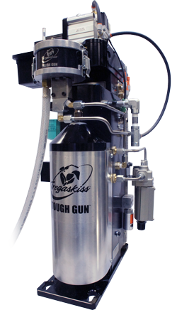
PRODUCT UPDATE – Expanded TOUGH GUN TA3 MIG Gun Offering
PRODUCT UPDATE —
Expanded TOUGH GUN TA3 MIG Gun Offering
Available Resources
Tips for Choosing the Right Contact Tip
Tips for Choosing the Right Contact Tip

Selecting the right material and bore size
Understanding contact tip recess
Recess/Extension Amperage Wire Stick-Out Process Notes 1/4-in. Recess > 200 1/2 – 3/4in. Spray, high-current pulse Metal-cored wired, spray transfer, argon-rich mixed gas 1/8-in. Recess > 200 1/2 – 3/4in. Spray, high-current pulse Metal-cored wired, spray transfer, argon-rich mixed gas Flush < 200 1/4 – 1/2in. Short-current, low-current pulse Low argon concentrations or 100 percent CO2 1/8-in. Extension < 200 1/4 in. Short-current, low-current pulse Difficult-to-access joints Extending contact tip life
PRODUCT IMPROVEMENT – Changes to Heavy Duty (HD) Nozzle Crimping
PRODUCT IMPROVEMENT –
Heavy Duty (HD) Nozzle Crimping
Affected Part Numbers
DISCONTINUED PRODUCT – Roughneck MIG Guns
DISCONTINUED PRODUCTS –
Miller Roughneck C-Series MIG GunsMiller Stock Number Roughneck Gun Model Number Bernard BTB MIG Gun Replacement Part Number Gun Length 194751 C-3010 10 ft. (3 m) 194752 C-3012 Q3012TE5EMC 194753 15 ft (4.6 m) 194754 C-4010 10 ft. (3 m) 194755 12 ft. (3.7 m) C-4015 Q4015TE5EMC 15 ft (4.6 m) C-5010 S5012GH5IMC 12 ft. (3.7 m) 194759 C-5015 15 ft. (4.6 m) Where To Order
Frequently Asked Questions (FAQs)
FasTip Consumables 300 amp 400 amp 500 amp Quik Tip Consumables 300 amp 400 amp 500 amp 

PRODUCT UPDATE – Spray Containment
PRODUCT UPDATE —
Spray Containment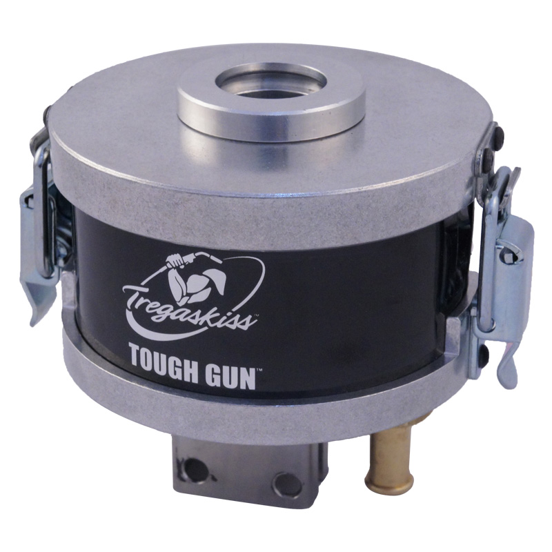
A perfect addition to the TOUGH GUN TT3 Reamer
Spray Containment Part Numbers
TS-1000-01 for use with Tregaskiss® Heavy Duty (HD) Nozzles (excluding 3/4″ bore) TS-1000-02 for use with Tregaskiss Standard Duty (SD) Nozzles TS-1000-03 for use with Tregaskiss Heavy Duty Nozzles with 3/4″ bore TS-1000-04 for use with Tregaskiss Heavy Duty Bottleneck Nozzles TS-1000-05 for use with Tregaskiss Standard Duty Bottleneck Nozzles New Automation Catalog Available from Tregaskiss
New Automation Catalog Available from Tregaskiss
Water-Cooled Robotic MIG Guns Can Reduce Consumable Costs and Downtime
Water-Cooled Robotic MIG Guns Can Reduce Consumable Costs and Downtime

Understanding water-cooled MIG guns
Selecting a water-cooled robotic MIG gun
Maintenance and usage tips
Consider the return on investment
Tregaskiss-Sponsored FIRST Robotics Team Attends World Competition
Tregaskiss-Sponsored FIRST Robotics Team Attends World Competition

Tregaskiss Sponsors Winning FIRST Robotics Team Headed to World Competition
Tregaskiss Sponsors Winning FIRST Robotics Team Headed to World Competition

Trends Associated with Robotic Welding Guns
Trends Associated with Robotic Welding Guns

The through-arm benefits
Increased cable durability, simplified replacement
Utilizing solid mounts
Creating more space, better joint access
More cooling options
Adding the extras
More to come
5 Things to Know About Robotic MIG Guns
5 Things to Know About Robotic MIG Guns

This article has been published as a web-exclusive on thefabricator.com. To read the entire story by Tregaskiss technical support specialist, Tom Whitter, please click here.
Money-Saving Tips for MIG Guns
Money-Saving Tips for MIG Guns

Tip No. 1: Protect the assets
Tip No. 2: Select the right neck
Tip No. 3: Perform regular inspections
Tip No. 4: Trim the liner properly
Tip No. 5: Select the best cable length for the job
Tip No. 6: Invest in consumables
Which is the Right MIG Gun? Tips for Making the Selection
Which is the Right MIG Gun? Tips for Making the Selection
Light- versus heavy-duty MIG guns

Air- versus Water-Cooled
Understanding and Extending Contact Tip Life
Understanding and Extending Contact Tip Life

Types of contact tip failure

Rectifying contact tip failure

• Properly selecting and installing the MIG gun liner
• Using shorter power cables when possible
• Eliminating loops or kinks in the power cable
• Using dust covers to protect the wire from contaminants that could clog the contact tip
The value of extending contact tip life
Tips for Making a MIG Gun Last on the Jobsite
Tips for Making a MIG Gun Last on the Jobsite

Choose a gun to fit the application
Some additional issues to consider when selecting a gun include:

Maintaining the gun

Care and maintenance can reduce costs
DISCONTINUED PRODUCT – TOUGH GARD Spatter Cleaner Robotic Nozzle Cleaning Station
DISCONTINUED PRODUCT — TOUGH GARD Spatter Cleaner Robotic Nozzle Cleaning Station

Equipment, Training, Maintenance and More: Best Practices for Successful Robotic Welding
Equipment, Training, Maintenance and More: Best Practices for Successful Robotic Welding
Manage parts and workflow

Protect against premature component failures
Don’t neglect maintenance?
• Checking for tight consumables connections.
• Confirming tool center point or TCP (discussed in more detail later).
• Checking for power cable wear and replacing as needed.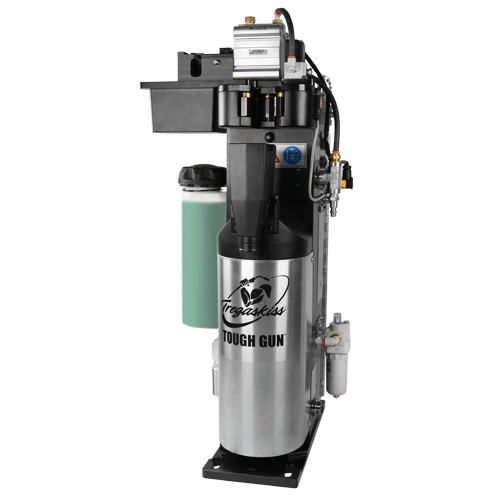
Always consider peripherals and robotic MIG gun extras
Stay on target
Find the right people
Protecting the investment
PRODUCT IMPROVEMENT – Bernard Conventional Liners
PRODUCT IMPROVEMENT –
Bernard Conventional Liners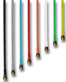
Bernard has implemented a material change to all Bernard conventional liners. All liners were previously produced from high carbon music wire. All liners will now be produced from high carbon music wire with tin zinc plated coating. Wire Size Liner Color 15′ (4.57 m) 25′ (7.62 m)
**Standard Liner for 1/16″ Guns4 Strategies for Improving Throughput in Robotic Welding Applications
4 Strategies for Improving Throughput in Robotic Welding Applications

ways to increase throughput in their overall robotic welding process,
while also keeping costs low and quality on par. 1. Streamline in-house processes
2. Seek out industry experts
3. Analyze key cost drivers
4. Continue the process
How to Choose the Right MIG Gun Liner
How to Choose the Right MIG Gun Liner
Various types of liners for the job
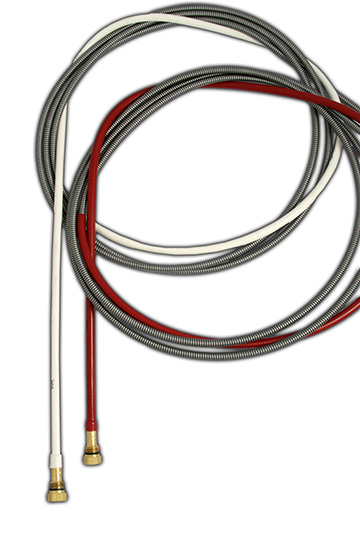
Closing thoughts
Tips for Proper Liner Installation to Help Optimize MIG Gun Performance
Tips for Proper Liner Installation to Help Optimize MIG Gun Performance
Various types of liners for the job

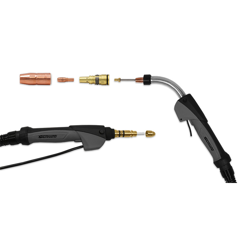
Step-by-step installation
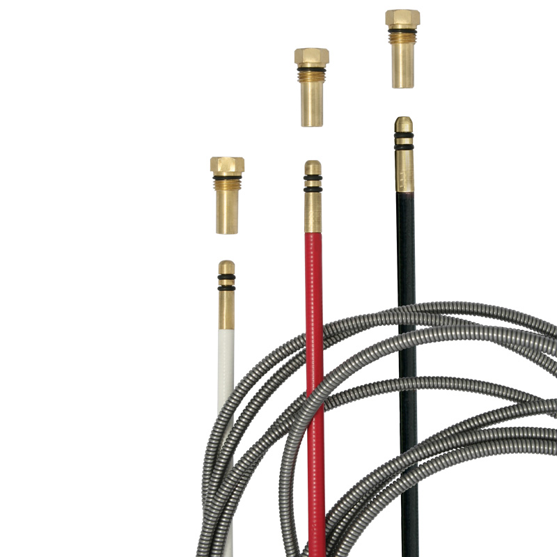
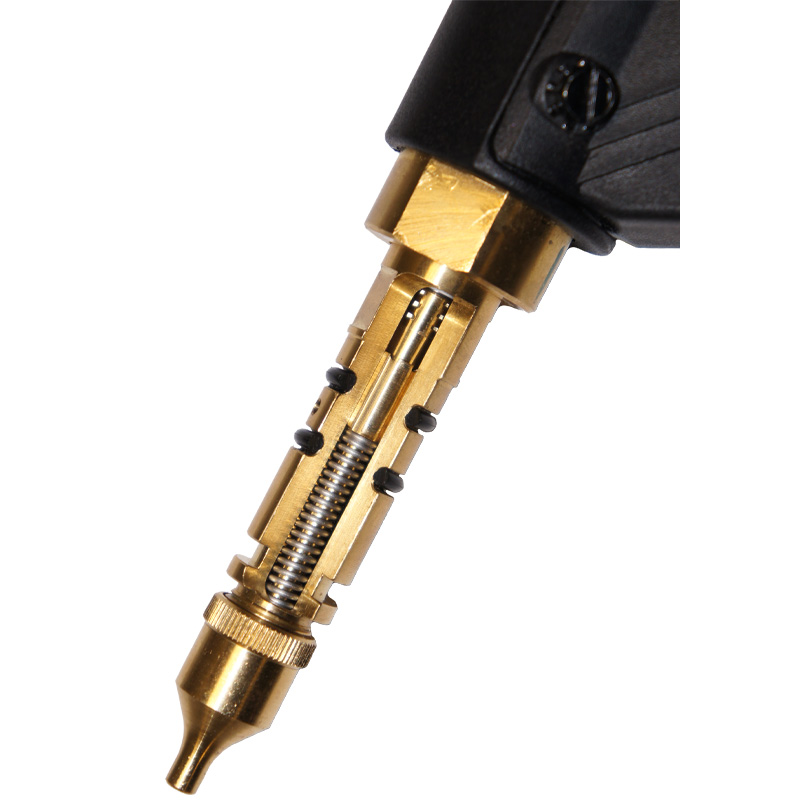
Proper liner installation can help optimize performance
Additional Resources
DISCONTINUED PRODUCT – Manual Products
DISCONTINUED PRODUCT –
Manual Products: Cable Connectors, Lugs and SplicersAs of August 4, 2014, the manual product line (cable connectors, lugs and splicers) from Bernard has been discontinued.
![]()


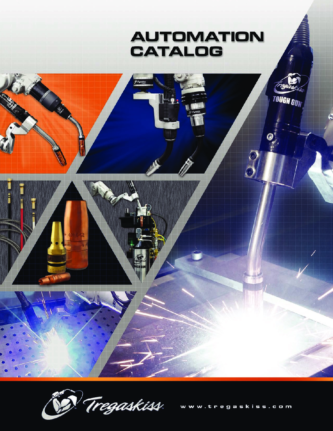