Configuring a MIG Welding Gun for Your Application
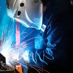
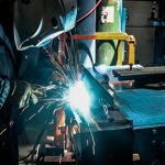
Have you struggled to gain proper joint access when welding? Or found yourself fatigued at the end of the day because of repeatedly welding in awkward positions? Configuring a MIG welding gun can help.
Why configure?
A MIG welding gun configured for the exact application can maximize efficiency and productivity. When you are more comfortable, you are able to weld longer. A customized MIG welding gun also reduces downtime for assembly, since it’s ready right out of the box. You can configure each welding gun part with online configurators like those from Bernard. These parts include the:
- Cable
- Handle and trigger
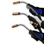
- Neck type, angle and length
- Consumables
- Power pin
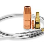
- Liner
How do you get started?
To configure the right MIG welding gun, look at the needs of your welding application. One answer influences the next choice.
- Determine the type and thickness of the base material on which you typically weld. This will dictate the welding wire selection and welding parameters, and in turn the amperage of MIG welding gun needed.
- Think about the expected arc-on time and length of the welds. Again, this impacts the amperage needed and also the duty cycle.
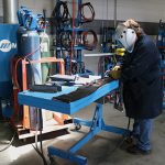
- Consider ergonomics. Decide what handle and neck style you prefer, as well as the cable length needed (shorter ones are lighter and easier to maneuver).
What affect does the weld cell have?
The physical space of the weld cell factors into MIG welding gun configuration. Consider these factors:
- If there are fixtures or jigs to work around, you may need narrower MIG welding consumables to access the joint.
- Space limitations and welding position impact cable length. Shorter cables are necessary for confined areas and are best for repetitive welding at a table since they are lighter. For out-of-position welds, a longer cable allows for greater movement (beware of coiling or kinking).
- The available workspace and joint access affect the length and bend angle of the gun neck you can use.
Taking the time to consider the factors that impact how you configure your MIG welding gun can go far in ensuring you have the exact one for your application.
See options for configuring a Bernard® MIG gun
This article is the first in a three-part series discussing how configuring a MIG gun can improve the welding operation, as well as what to consider in the process. Read article two, How to Choose Welding Gun Parts, and article three, Selecting the Right MIG Welding Consumables.
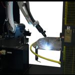
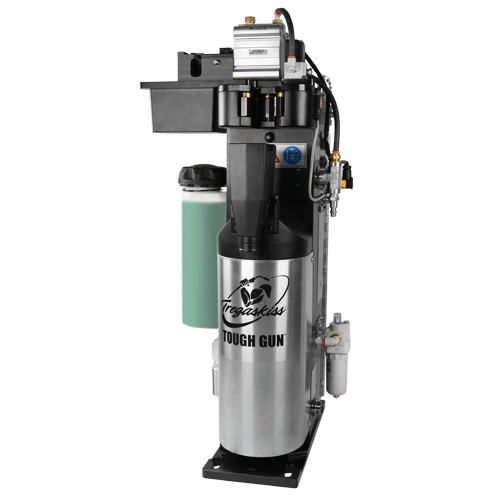
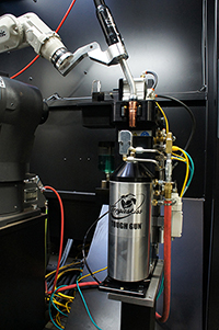
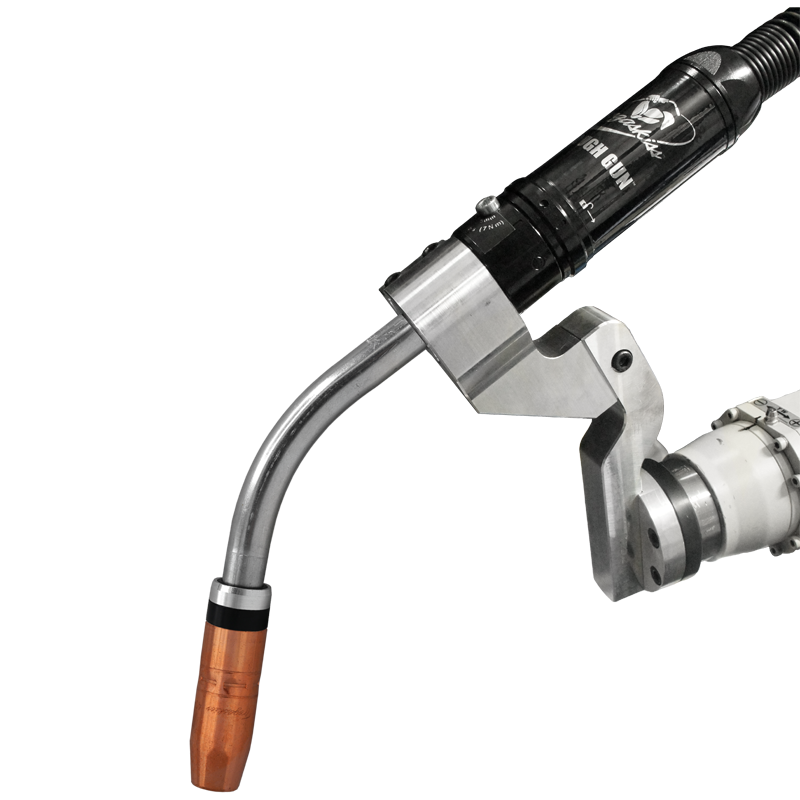
WINDSOR, Ontario (August 20, 2019) – Tregaskiss has updated the online configurators for its TOUGH GUN® CA3 robotic air-cooled MIG gun, TOUGH GUN TA3 robotic air-cooled MIG gun and the TOUGH GUN TT3 reamer robotic nozzle cleaning station with improved functionality. The new mobile-friendly configurators allow users to quickly and easily customize their robotic MIG guns and reamer for their exact application. Designed for high-volume production environments, the 385-amp TOUGH GUN CA3 robotic air-cooled MIG gun is engineered for precision, durability, accuracy and repeatability. The TOUGH GUN TA3 robotic MIG gun minimizes downtime and improves welding performance on today’s through-arm robotic welding systems, while the TOUGH GUN TT3 and TT3 (Ethernet) reamer helps extend the life of robotic MIG guns and consumables and operates reliably in even the harshest welding environments. In addition to features previously offered on the configurators, including reverse part number lookups and step-by-step product customization, the new versions provide access to expanded resources. These include a detailed summary of the configured gun or reamer, downloadable exploded view diagrams, an expanded replacement parts list with diagram, and other valuable takeaways like spec sheets and owner’s manuals. When the configurations for the TOUGH GUN CA3 and TOUGH GUN TA3 Robotic MIG Guns or TOUGH GUN TT3 Reamer are complete, the user receives a part number and parts list, and has the option to print, save in PDF format or email results. There is also the option to find contact information for a local distributor to order products from, or the user can request more information from a Customer Service representative. To access the newly updated online configurators, visit Tregaskiss.com/ConfigureMyGun. # # #
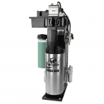
August 20, 2019 Effective immediately, a new, enhanced AccuLock™ S power pin is now available for Miller® equipment. This new power pin is designed specifically for use with the new Bernard® AccuLock S consumable system to optimize performance. Load and Lock for Better Productivity Learn more about AccuLock S consumables.
July 1, 2018 Tregaskiss has made changes to its 5-Gallon (18.9 L) TOUGH GARD® anti-spatter liquid pail design for increased strength and durability. Designed with a heavy duty integrated handle, this new container is easier to handle and can be easily stacked for maximized storage space. The new design also offers an improved seal to eliminate spillage during shipping. Like the former pail design, this new 5-Gallon container is compatible with the TOUGH GARD anti-spatter multi-feed system. Learn more about TOUGH GARD anti-spatter liquid or the TOUGH GARD anti-spatter multi-feed system.
MIG welding consumables are a critical but often overlooked part of the welding operation. Unfortunately, without a clear understanding of the problems that can arise with consumables — and the best way to fix them — companies stand to lose productivity, jeopardize quality and increase costs. In some cases, the biggest issue is choosing the wrong consumable for the job. Consider this real-life example: A company with 90 arcs is using five contact tips per day, per welder — that adds up to 450 contact tips a day. By simply changing to a more robust consumable system, the company could potentially use one contact tip per welder every three to four days. The savings in reduced downtime and purchasing costs in this situation is significant. So how can companies avoid common pitfalls? A willingness to look at the impact of welding consumables on the overall operation — not just the product purchase price — is key. Training is also a vital part of success. Welding operators and maintenance personnel should know how to properly select, install and maintain consumables and troubleshoot problems when they arise. Or better yet, understand how to prevent them in the first place. Welding nozzles play an important role in the welding operation, directing shielding gas to the weld pool to protect it from contaminants. Incorrect contact tip recess within the welding nozzle is among the biggest problems. The more the contact tip is recessed, the longer the wire stickout, which can lead to an erratic arc and increased spatter in the nozzle. It can also negatively impact shielding gas coverage. In approximately 90% of applications, a 1/8-inch contact tip recess provides the best shielding gas coverage with a welding wire stickout that helps support consistent arc stability. Using the wrong welding nozzle for the application can cause downtime for changeover due to premature failure. For a standard welding application (100 to 300 amps), a copper nozzle provides good heat resistance. Copper nozzles also resist spatter buildup. For higher-amperage applications (above 300 amps), a brass welding nozzle is the better choice. Brass does not anneal as fast as copper, so the welding nozzle will maintain its hardness longer under higher temperatures. Choosing the wrong shape and size of nozzle can be problematic. Too large of a nozzle can make it difficult to obtain the joint access needed to complete a sound weld. Long or short tapered nozzles work well for restricted joints. However, there is an increased risk of spatter buildup due to the narrower bore, which can shorten the consumable’s life. To gain good gas coverage, use a longer nozzle when possible. MIG welding contact tips provide the current transfer to the welding wire to create an arc. Using a contact tip with an inside diameter (ID) that’s too small can lead to poor wire feeding and, potentially, a burnback. Using a tip with too large of an ID can cause the welding wire and arc to wander. Every consumables manufacturer has proprietary formulas for gauging contact tip ID and implementing it into their design. Select a high-quality contact tip for consistent tolerances, and match the contact tip ID to the diameter of the welding wire to gain the best electrical conductivity. This happens because the contact tip ID is actually slightly larger than the specified measurement. For example, pairing a contact tip with an ID of 0.035 inch and a wire with the same diameter allows the wire to feed smoothly through the bore, connecting enough to generate a stable welding arc. The wrong contact tip outside diameter (OD) can also cause problems. For higher amperage applications, use a contact tip with a larger OD to better withstand heat. 1. Copper contact tips provide good thermal and electrical conductivity for light- to medium-duty applications. 2. Chrome zirconium contact tips are harder than copper ones and are good for higher-amperage applications. They are also a good option if a company experiences ongoing instances of keyholing — oblong wear on the bore that can lead to an unstable arc and premature contact tip failure. 3. Contact tips are available in the marketplace that feature proprietary materials and design. These tips cost more than copper or chrome zirconium contact tips but have been shown to last more than 10 times as long. They are designed for pulsed, spray transfer or CV MIG welding. Cross-threading the contact tip is another issue that can lead to downtime. When a contact tip isn’t threaded properly during installation, or if the welding operator introduces dirt or debris to the threads, the gas diffuser can be damaged during installation. This will require replacement and increase costs. To avoid cross-threading, look for contact tips with coarse threads that install with fewer turns. The welding liner has a single and relatively simple purpose: to guide the welding wire from the wire feeder through the power cable to the contact tip. However, it is capable of causing significant problems if it isn’t installed properly. Trimming a liner incorrectly is the most common installation error. A liner that is too short lessens the support of the welding wire as it passes through the length of the gun. This can lead to micro-arcing or the formation of small arcs within the contact tip. Micro-arcing causes welding wire deposits to build up in the tip, resulting in an erratic arc and burnbacks. In more extreme cases, micro-arcing can cause MIG gun failure due to increased electrical resistance throughout the front-end consumables and gun neck. It may also prompt the welding operator to increase voltage in an effort to rectify poor welding performance, which can cause the gun to overheat. On the other hand, a too-long welding liner can lead to kinking and poor wire feeding. When trimming a conventional welding liner, avoid twisting it and use a liner gauge to ensure the proper measurement. There are also consumable systems available that provide error-proof liner installation and require no liner measuring. The gas diffuser locks the liner in place while concentrically aligning it with the power pin and contact tip to eliminate any gaps. The welding operator or maintenance personnel feeds the liner through the neck of the gun, locks it in place and cuts the liner flush with the back of the power pin. As with contact tips, remember that quality matters when it comes to welding liners. Always select a stiffer liner, so it is capable of supporting the wire as it feeds from the spool through the power pin and the length of the gun. Paying close attention to MIG gun consumables is important to gaining good welding performance. That means looking at the overall quality of the products being purchased; the manner in which they are inventoried, stored and handled; and how they are being installed. Always follows the consumable manufacturer’s recommendations, and when in doubt, contact their customer service or a trusted welding distributor for help.
Using the wrong shielding gas for MIG welding applications — or having improper gas flow — can significantly impact weld quality, costs and productivity. Shielding gas protects the molten weld pool from outside contamination, so it’s critical to choose the right gas for the job. Learn more about which gases and gas mixes are best suited for certain materials, along with some tips for optimizing gas performance — and saving money — in your welding operation.
August 8, 2019 Tregaskiss is proud to announce that we have launched the following new conversion diffusers that receive TOUGH LOCK® contact tips, including HDP: Fronius® TPS 400i Lincoln® Magnum Pro® (Slip-On) Lincoln Magnum Pro (Thread-On) Learn more about TOUGH LOCK consumables.
August 1, 2019 To continue delivering sustainable value to our customers, we regularly assess our product offering to ensure focus and opportunities to innovate our product portfolio. Accordingly, due to low demand, we are discontinuing the 500 amp B Series Handle option from our BTB MIG gun offering. Effective August 16, 2019, the following part numbers will no longer be available: Please note that a comparable replacement is the O Series Handle option, which is also configurable in our BTB MIG gun product line. Learn more about Bernard® BTB MIG guns and available options, or configure a BTB MIG gun.
BEECHER, Ill./WINDSOR Ontario. (July 18, 2019) – Bernard and Tregaskiss will attend FABTECH 2019 in Chicago at McCormick Place, November 11 to 14. The companies will be in booth B23054. In addition to showcasing AccuLock™ consumables for semi-automatic and robotic welding applications, the companies will also participate in live welding demonstrations. As part of those demonstrations, the Bernard® AccuLock S consumables will be paired with Bernard semi-automatic MIG guns, power sources from Miller Electric Mfg. LLC and filler metals from Hobart in a shared area with these brands. Both Bernard and Tregaskiss will have representatives available to answer questions about semi-automatic and robotic MIG gun and consumable solutions and provide information on the companies’ technical and product support. # # #
July 30, 2019 Tregaskiss has made the following changes to its TOUGH GUN® reamer cutter blades: The above changes will be implemented as a running change and will be sold under the same part numbers as the previous design.
Robotic MIG welding guns and consumables are an important part of the welding operation yet are frequently overlooked when investing in robotic welding systems. Companies may often choose the least expensive option when, in reality, purchasing quality robotic MIG guns and consumables can lead to significant cost savings in the long run. There are many other common misconceptions about robotic MIG guns and consumables that, if corrected, can help increase productivity and decrease downtime for the entire welding operation. Here are five common misconceptions about MIG guns and consumables that may be affecting your robotic weld cell.
June 18, 2019 To continue delivering sustainable value to our customers, we regularly assess our product offering to ensure focus on customer needs and opportunities to innovate our product portfolio. Accordingly, this is a notification that we are discontinuing Tregaskiss® SURESTART™ contact tips, due to low demand. Effective immediately: All SURESTART contact tips have been discontinued and no longer available for sale. Visit the TOUGH LOCK consumables page for more information.
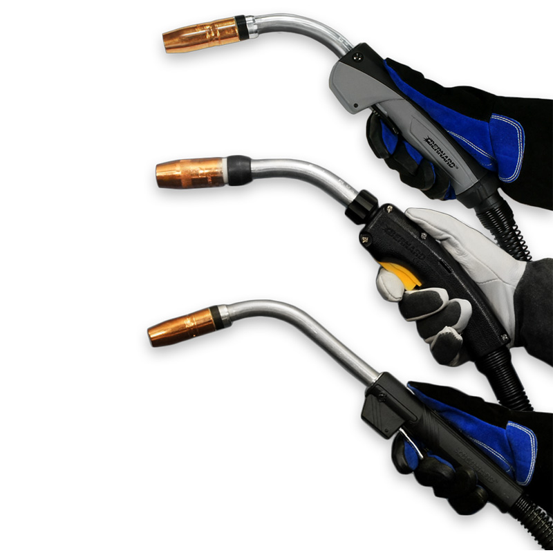
It’s important for new welding operators to establish proper MIG techniques in order to achieve good weld quality and maximize productivity. Safety best practices are key, too. It’s just as important, however, for experienced welding operators to remember the fundamentals in order to avoid picking up habits that could negatively impact welding performance. From employing safe ergonomics to using the proper MIG gun angle and welding travel speeds and more, good MIG welding techniques provide good results. Here are some tips. A comfortable welding operator is a safer one. Proper ergonomics should be among the first fundamentals to establish in the MIG welding process (along with proper personal protective equipment, of course). Ergonomics can be defined, simply, as the “study of how equipment can be arranged so that people can do work or other activities more efficiently and comfortably.”1 The importance of ergonomics for a welding operator can have far reaching effects. A workplace environment or task that causes a welding operator to repetitively reach, move, grip or twist in an unnatural way, and even staying in a static posture for an extended period of time without rest. All can lead to repetitive stress injuries with life-long impacts. Proper ergonomics can protect welding operators from injury while also improving productivity and profitability of a welding operation by reducing employee absences. 1. Using a MIG welding gun with a locking trigger to prevent “trigger finger”. This is caused by applying pressure to a trigger for an extended period of time. 2. Using a MIG gun with a rotatable neck to help the welding operator move more easily to reach a joint with less strain on the body. 3. Keeping hands at elbow height or slightly below while welding. 4. Positioning work between the welding operator’s waist and shoulders to ensure welding is being completed in as close of a neutral posture as possible. 5. Reducing the stress of repetitive motions by using MIG guns with rear swivels on the power cable. 6. Using different combinations of handle angles, neck angles and neck lengths to keep the welding operator’s wrist in a neutral position. The proper welding gun or work angle, travel angle and MIG welding technique depends on the thickness of the base metal and the welding position. Work angle is “the relationship between the axis of the electrode to the welders work piece”. Travel angle refers to employing either a push angle (pointing in the direction of travel) or a drag angle, when the electrode is pointed opposite of travel. (AWS Welding HandBook 9th Edition Vol 2 Page 184)2. When welding a butt joint (a 180-degree joint), the welding operator should hold the MIG welding gun at a 90-degree work angle (in relation to the work piece). Depending on the thickness of the base material, push the gun at a torch angle between 5 and 15 degrees. If the joint requires multiple passes, a slight side-to-side motion, holding at the toes of the weld, can help fill the joint and minimize the risk of undercutting. For T-joints, hold the gun at a work angle of 45 degrees and for lap joints a work angle around 60 degrees is appropriate (15 degrees up from 45 degrees). In the horizontal welding position, a work angle of 30 to 60 degrees works well, depending on the type and size of the joint. The goal is to prevent the filler metal from sagging or rolling over on the bottom side of the weld joint. For a T-joint, the welding operator should use a work angle of slightly greater than 90 degrees to the joint. Note, when welding in the vertical position, there are two methods: weld in an uphill or a downhill direction. The uphill direction is used for thicker material when greater penetration is needed. A good technique for a T-Joint is call the upside-down V. This technique assures the welding operator maintains consistency and penetration in the root of the weld, which is where the two pieces meet. This area is the most important part of the weld.The other technique is downhill welding. This is popular in the pipe industry for open root welding and when welding thin gauge materials. The goal when MIG welding overhead is to keep the molten weld metal in the joint. That requires faster travel speeds and work angles will be dictated by the location of the joint. Maintain a 5 to 15 degree travel angle. Any weaving technique should be kept to a minimum to keep the bead small. To gain the most success, the welding operator should be in comfortable position in relation to both the work angle and the direction of travel. Wire stickout will change depending on the welding process. For short-circuit welding, it is good to maintain a 1/4- to 3/8-inch wire stickout to reduce spatter. Any longer of a stickout will increase electrical resistance, lowering the current and leading to spatter. When using a spray arc transfer, the stickout should be around 3/4 inch. Proper contact-tip-to-work distance (CTWD) is also important to gaining good welding performance. The CTWD used depends on the welding process. For example, when using a spray transfer mode, if the CTWD is too short, it can cause burnbacks. If it’s too long, it could cause weld discontinuities due to lack of proper shielding gas coverage. For spray transfer welding, a 3/4-inch CTWD is appropriate, while 3/8 to 1/2 inch would work for short circuit welding. The travel speed influences the shape and quality of a weld bead to a significant degree. Welding operators will need to determine the correct welding travel speed by judging the weld pool size in relation to the joint thickness. With a welding travel speed that’s too fast, welding operators will end up with a narrow, convex bead with inadequate tie-in at the toes of the weld. Insufficient penetration, distortion and an inconsistent weld bead are caused by traveling too fast. Traveling too slow can introduce too much heat into the weld, resulting in an excessively wide weld bead. On thinner material, it may also cause burn through. When it comes to improving safety and productivity, it’s up to the experienced veteran welding operator as much as the new welding to establish and follow proper MIG technique right. Doing so helps avoid potential injury and unnecessary downtime for reworking poor quality welds. Keep in mind that it never hurts for welding operators to refresh their knowledge about MIG welding and it’s in their and the company’s best interest to continue following best practices. 1. Collins Dictionary, “ergonomics,” collinsdictionary.com/dictionary/english/ergonomics.
The potential advantages of robotic welding are well known — increased productivity, improved quality and greater cost savings compared to semi-automatic welding. But the question is: How do companies best implement this technology to gain these benefits? And how can they ensure a quick return on the investment (ROI)? Simply stated, planning. More preparation upfront helps minimize the cost and time for correcting errors in the robotic welding system once it has gone into production. From the welding power source to the robot or weld process to the gun and consumables, each component should be thoroughly researched to make sure it is feasible to operate in the weld cell — not just on paper, but in reality. Take advantage of turnkey integrators who run their own process and capability studies. They can provide useful double checks to a plan and often conduct reach studies that model the weld tooling and workpiece. These mock up how the robot would weld in the finished system to test the gun reach and the overall efficiency of the process. Also remember, success in robotic welding is as much a matter of doing the right thing as it is avoiding pitfalls that could hinder the efficiency of the operation. With planning comes budgeting. A robotic welding cell may be installed on time, produce good weld quality and meet cycle time, but if the implementation and use of the system is over budget it will be an uphill battle to gain a good ROI. Consider the associated goals to help establish a feasible ROI. For example, a company with the goal of producing 1000 parts a day needs to determine how much it can make from those parts. From there, it would subtract the cost of utilities and labor, along with the cost to make the product and the cost of raw materials, to determine a budget on equipment costs that would make the company profitable. If this equipment will only be used for 5 years, the company may need a quicker ROI than if it’s planning to use the robotic welding system for 10 years or more. Companies can make the most of their budget by considering equipment that could be reused. This can cut down on the investment in the long run. Robots can have an extensive life if maintained well, allowing them to be re-purposed from project to project. The same holds true with welding power sources and nozzle cleaning stations. Ultimately, ROI depends on the company and what practices it follows for making profit. Some may be able to allow the equipment to take 18 months or more to pay for itself if the company plans on re-using or re-purposing the welding robots on multiple platforms over the next 10 years. Others may stand by the goal of a one-year ROI, which is common. Proper training is important for keeping a robotic welding system running successfully and profitably in the long term. Robot integrators and other equipment manufacturers often offer training as part of the implementation process. This training provides welding operators with a knowledge of robotic welding in general, as well as providing the information they need to operate the robot effectively for the application at hand. A well-trained operator will also be able to determine ways to maximize the efficiency of the robotic weld cell. They do this by troubleshooting and resolving issues quickly, keeping the robot online and supporting greater productivity and cost savings. Likewise, train welding operators to implement PM for the robotic gas metal arc welding (GMAW) gun to gain longer life, reduce downtime and achieve more arc-on time. Regularly check that the gun connections, consumables and power pin are secure. Look for any signs of power cable wear and replace if necessary.Training geared toward the preventive maintenance (PM) of a robotic welding system and the weld cell is also key. For example, spatter build-up on the robotic welding gun can cause grounding issues and build-up on tooling may lead to dimensional movement of the steel from cycle to cycle. The latter can block the datum placements causing gun reach issues. In a worse-case scenario, spatter builds up on equipment over time, creating solid formations that are difficult to remove and prevent the re-use of the equipment. To avoid these problems, train operators to follow a regular cleaning schedule for the weld cell and the equipment. There are several common mistakes that can negatively affect productivity and quality in a robotic welding system. Knowing how to avoid these can help companies make the most out of the equipment and gain greater success. Consider the following: 1. Implementing the wrong equipment in a robotic welding cell can lead to spending more money than is required. Be sure to rate the power source, robotic GMAW gun and consumables for the application. Doing so helps minimize the risk of premature equipment failures that can lead to unplanned downtime and costly equipment replacement. For example, if a company selects an air-cooled system, but actually requires a water-cooled system for the application, it could incur unnecessary costs to repair or upgrade a failed robotic GMAW gun system that cannot handle the heat. 2. Underutilizing the robotic welding system can prevent companies from realizing their full productivity potential. Robotic welding systems should be programmed to maximize the arc-on time during the weld process cycle. In some cases, it may be possible to have fewer robots that weld for slightly longer cycles. This helps drop the initial implementation costs. Take this example. A company has four robots in cell welding at 30 inches per minute with a cycle time of 60 seconds. These robots are inefficient since they are only welding half of the cycle time. That could be due to the positioner rotating for weld access, too slow of robot air cut movements, poor welding angles or other limiting factors. In this scenario, the total length of completed welds for all four robots is 60 inches (30 in. / min. x 1 min. / 60 seconds x 30 seconds of welding per robot = 15 inches of weld per robot). An alternative here is to keep the cycle time at 60 seconds and drop down to three robots by improving items like the weld angles, creating quicker air cuts between welds, utilizing gun reaming during positioner movements and more. Now with improvements, the robots could weld at an average of 35 inches per minute for 35 seconds each cycle. That provides an average of 20 inches of weld per cycle per robot, allowing for the same total of 60 inches of weld with one less robot. 3. Underutilizing available labor can also hinder productivity. While companies should take care not to overload operators, it’s important to balance manpower in robotic welding process so that employees are efficient and busy at the same time. If an operator is idle waiting for the weld cycle to complete, there could be room for process improvements by allocating labor to other activities near the weld cell. 4. Poor tooling design can impede quality. Thoroughly plan the tooling design and understand how the parts being welded will impact it. Different parts and materials react differently to heat and may draw, flex or bend during the welding process. Factor in how much heat a given weld sequence generates. The tooling will have to be designed with these in mind. If possible, design tooling to permit welding in the flat or horizontal position with appropriate robotic GMAW gun access. This allows for faster and more consistent results. Finally, remember, less expensive tooling may be attractive when looking at upfront costs, but it can be a pitfall later if it doesn’t meet the demands of the job. 5. Overlooking activities outside the robotic weld cell can be detrimental. Plan for part inspection and cosmetic rework, as well as the final stages of palletizing the product if that is part of the operation. Some of these processes can be automated or manual labor driven. These are key stages in a robotic welding operation that can quickly become bottlenecks that cause the entire process to slow down. These bottlenecks can also add unplanned manpower or equipment costs, which can become expensive. Remember that no plan for welding automation can be successful without a good schedule for its implementation. Being thorough is more important than being fast. Set realistic goals for completing the installation of the robotic weld cells and don’t rush or over-complicate the process. For first-time investors in robotic welding starting small can also help ensure greater success. Once the robotic weld cell or cells begin operating, keep in mind that the startup may not be perfect. There may be adjustments required to optimize performance to gain the best productivity and quality.
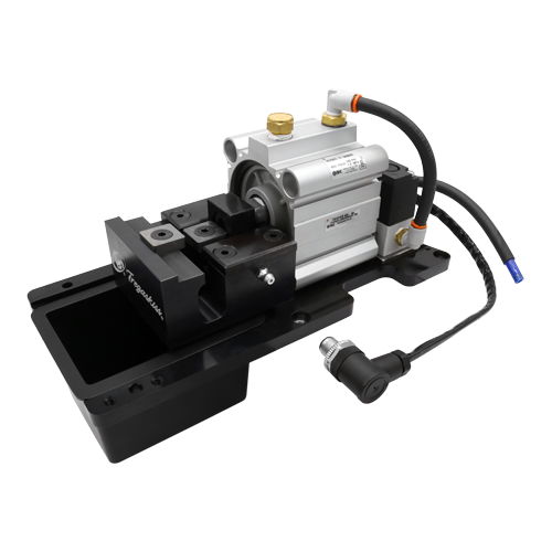
From reamers or nozzle cleaning stations to wire cutters and anti-spatter sprayers, welding peripherals and accessories can contribute significantly to the success of a robotic welding operation. In addition to improving weld quality, they can also help companies maintain high levels of productivity. Reamers, in particular, are most prevalent in automotive manufacturing, where uptime and quality are critical. This peripheral cleans the welding consumables — for example, welding nozzles and gas diffusers — free of spatter, and most automotive welding operations rely on the process after virtually every weld cycle. Other industries, such as heavy equipment manufacturing, also employ reamers and other peripherals in their robotic welding operations, as do some general manufacturers. It’s not by chance that peripherals work the way they do. Like any equipment, caring for them with routine preventive maintenance (PM) is important to gaining optimal performance and longevity. A reamer requires regular attention since it operates frequently during the weld cycles. Its job is important though, as it performs essential welding nozzle cleaning that helps keep the robotic welding cell up and running and quality on par. With the PM for this equipment also comes PM for its associated accessories: the lubricator, cutter blades and anti-spatter sprayer. All require varying levels of PM activities — some daily, weekly, monthly or yearly. In addition to inspecting the consumables for wear and replacing as needed, follow this PM routine on a daily basis: On a weekly basis, continue to examine the integrity of the consumables and follow these guidelines: Monthly PM for reamers and accessories requires less steps but is more intensive. It may require scheduling a time off cycle to complete. Lastly, on an annual basis: While it may seem time-consuming to implement these PM measures, they can typically be completed during routine pauses in production. More intensive activities can be scheduled so as to prevent interruption to production. Ultimately, the PM is time well spent and can help protect the investment in the reamer and its accessories. Wire cutters are increasingly being used in automotive and other manufacturing operations. This equipment is integrated into a reamer configuration and used in conjunction with a wire brake on the robotic MIG gun. The wire brake prevents the welding wire from moving, while the wire cutter cuts it at a set distance. This allows for a consistent wire stickout so the robot can touch sense and track the joint before welding. The results are more accurate weld placement and smooth arc starting. PM for wire cutters is relatively simple. Peripherals like reamers with anti-spatter sprayers and wire cutters can help companies realize a greater return on their investment in a robotic welding system. They aid in high weld quality, minimize rework and help meet productivity goals. Train welding operators to follow recommended PM activities as a part of a routine care of the weld cell. The time and cost to care for them properly will be small in comparison to the improvements they can provide to the bottom line.
When MIG welding consumables aren’t properly installed or maintained, it can result in wire- feeding issues and weld quality problems. Troubleshooting and correcting these challenges can cost hundreds of dollars — and hours per day — in a manufacturing operation. As the industry faces a shortage of skilled welders and those entering the profession have less experience, it may be more common for welders to incorrectly install MIG gun consumables and liners. Consumables that simplify the installation process can help eliminate errors, reduce downtime for changeover and troubleshooting, and decrease costs. Learn how new consumables available in the marketplace can help address wire-feeding problems and the role they play in maximizing throughput and productivity. Not addressing poor consumable performance can result in, among other problems, lower-quality parts and expensive rework. Wire-feeding issues are some of the most common complaints in the welding industry. Often, improper trimming or installation of the MIG gun liner is the cause of these problems. As with other consumables, the MIG gun liner wears out over time and must be changed periodically. Typically, replacement liners are longer than necessary and must be trimmed appropriately for the style and length of the MIG gun. Trimming the liner to the proper length can be difficult. In some cases, the welder may change the liner without taking the time to complete the proper steps of installation or may not know the proper steps. This can result in a host of problems. A liner that is cut too short can lead to the issues a lot of welders experience: wire chatter, erratic arc and burnback. A too-long liner, which happens less frequently, results in a tight fit and can cause the wire to weave and curve as it feeds through the gun. If the operator continues to weld without diagnosing the cause of any of these problems, it may result in bad welds that require rework or result in scrap. It seems to be common in the industry that welders typically change the contact tip at the first sign of trouble with the welding gun, and this may help for a short-term fix. But if the liner is the root cause, the problem will repeat itself, leading the welder to use more tips than if a correctly trimmed liner was installed. This increases costs due to wasted consumables and downtime for changeover. In some operations, welders don’t install or trim liners. Instead, MIG guns are taken to a maintenance department whenever a liner must be changed. This adds downtime and costs and decreases throughput in the operation. Solutions that are designed to address liner trim length errors and poor wire feeding can reduce troubleshooting, downtime and rework — ultimately saving money. The AccuLock™ S consumables system from Bernard® take the guesswork out of liner trimming and installation in semi-automatic welding operations. The system offers an error-proof liner replacement process that eliminates measuring and incorrectly trimming liners. In contrast to most MIG gun liners that load from the back of the gun, AccuLock S liners load through the neck at the front of the gun. The liner is then locked and trimmed flush with the power pin at the back of the gun, which eliminates the need to measure. This design also eliminates doubt about proper liner length — and the time spent troubleshooting liner trimming issues — because operators can simply look at the back end of the gun to see that the liner is correctly trimmed and in place. With traditional MIG guns, welders can’t see if a liner is cut too short, since the end of the liner that’s been trimmed is hidden under the nozzle and gas diffuser. A welder would have to remove all the consumables to see the liner inside the gun. In addition, the system optimizes wire feeding because the liner is locked and concentrically aligned to both the contact tip and the power pin without the use of fasteners. Capturing the liner at both ends of the gun keeps the liner from extending and contracting based on gun position — and it allows for a flawless wire-feeding path. Typically, the longer the welding gun, the more the cable bends and twists. Even when a traditional liner is perfectly cut and installed, the liner gets pushed forward and back inside the gun as it’s used, since the liner is affixed at the back end of the gun but free floating at the front end of the gun. This liner movement can result in wire chatter and erratic arc. When the liner is affixed at both ends of the gun, as with the AccuLock S consumables system, welders are assured the liner won’t pull back, or push into the contact tip — allowing for smooth, uninterrupted delivery of the wire to the weld pool. And because the liner is concentrically aligned with the contact tip, it creates less mechanical wear on the tip’s interior diameter, possibly leading to longer life by reducing the risk of keyholing associated with misaligned liners and contact tips. Reducing keyholing also lessens the opportunity for an erratic arc, excessive spatter and burnback, all issues that shorten contact tip life. Additional features of the new consumables system also contribute to optimized MIG gun performance: Cool, connected contact tip: Sixty percent of the AccuLock contact tip is buried in the gas diffuser to protect it from heat damage. As the shielding gas flows through the gun, it cools the contact tip tail inside the gas diffuser, which helps reduce heat and wear. These features differ from traditional tips that screw onto the gas diffuser with little to no portion of the contact tip exposed directly to the shielding gas as it exits the diffuser to the arc. A tapered design of the consumables tightly locks the conductive parts together to minimize electrical resistance and further reduce heat buildup. Versatile nozzle: A patent-pending nozzle design allows operators to choose thread-on or slip-on — with the same nozzle part number. Typically, nozzles are either thread-on or slip-on style, a choice that often comes down to welder preference. A thread-on nozzle is locked in, while a slip-on nozzle can be adjusted to different heights and easily pulled off. With AccuLock S consumables, the same nozzle can be used as a slip-on or thread-on nozzle, and the change is determined by using a different diffuser. This allows operations to greatly simplify their consumables inventory and changeover, with fewer parts to manage. In addition, a steel retaining ring and friction lock on the diffuser help prevent the nozzle from unthreading or loosening when it’s threaded on. This also helps eliminate the potential for gas leaks at the back of the nozzle or insufficient gas coverage of the weld — a common occurrence when traditional thread-on nozzles loosen over time. Coarse threads: The AccuLock contact tip features coarse threads, making it less likely to become cross-threaded and also requires fewer turns to install or remove — speeding up tip replacement. One full turn disengages the contact tip from the diffuser. Significant time and money can be spent troubleshooting weld quality problems and wire- feeding issues, such as erratic arc, bird-nesting and burnback. In addition, many welding operations are dealing with increasing welder retirements and turnover, which can increase troubleshooting time associated with less experienced welders installing consumables. The AccuLock S consumables system is designed to eliminate liner trimming errors and optimize wire feeding to help operations reduce downtime, costs and rework — maximizing throughput and efficiency.
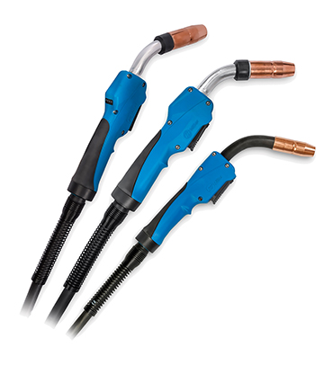
BEECHER, Ill. April 9, 2019 – Bernard has launched new versions of its BTB semi-automatic air-cooled MIG gun and Clean Air™ fume extraction gun online configurators. These mobile-friendly configurators make it easy for users to customize an industrial-duty welding gun to match their application or preferences — improving comfort and overall welding performance. Configuring a gun to users’ exact specifications can help reduce fatigue and stress, making them more productive and helping them gain high quality welds. Users can still take advantage of the configurator features offered previously, including reverse part number lookups — now with extended functionality and additional resources available. These online configurators let customers choose the specifications of their gun, including cable type and length, amperage, handle and trigger type, neck type, neck angle and length, contact tip, wire size, power pin and liner. Plus, the new Bernard® AccuLock S consumables are now available for selection in the BTB semi-automatic air-cooled MIG gun configurator. Once the configuration is complete, users receive a part number and a detailed summary of their results. In addition, users now have access to new exploded view diagrams of the welding gun and consumables, product spec sheets and an owner’s manual, as well as other relevant online resources and literature. Users can choose to print the results of their gun configuration, download them in PDF format and save them for later, or share via email, and can request more information from a Bernard representative directly on the site. They can also take the part number to their local distributor to order their gun. Learn more or access these online configurators now. # # #
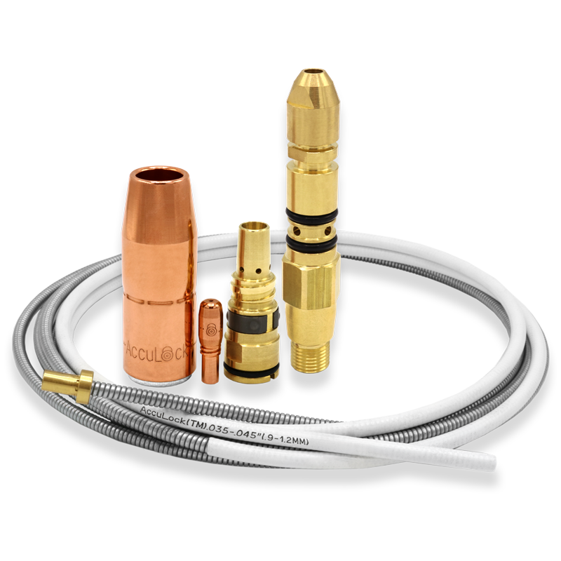
BEECHER, Ill. March 6, 2019 – Bernard has introduced its new AccuLock™ S consumables system. Building on proven MIG gun consumable technology, Bernard has added advanced design features. These features ensure higher productivity and optimized wire feeding, while also simplifying installation and maintenance. The system includes a contact tip, nozzle, gas diffuser, liner, and power pin and power pin cap. “AccuLock S consumables represent a revolutionary improvement for users of industrial MIG guns,” says Linda Ray, Vice President and General Manager. “These MIG gun consumables work together, as a complete system, improving performance and minimizing — if not eliminating — the most common gun maintenance issues.” The AccuLock S consumables are designed to solve issues associated with poor wire feeding in semi-automatic MIG welding such as bird-nesting, burnback and erratic arc. The system locks in place and concentrically aligns the liner with the power pin and contact tip. This allows for a flawless wire feeding path with no gaps or misalignments. Additionally, this does not require liner measuring during installation or replacement. Welders simply cut the liner flush with the back of the power pin for perfect liner trimming — every time. Combined, these features decrease the risk of improper installation. Moreover, this decreases the possibility of costly downtime to address poor weld quality or liner replacement. Adding to the ease of installation, the contact tips feature coarse threads that easily mate with the gas diffuser, lessening the chance of cross-threading and speeding contact tip replacement. By design, the Acculock S MIG gun consumables reduce heat buildup, improving product life. Sixty percent of the contact tip is buried in the gas diffuser to protect it from heat damage. The shielding gas helps cool the contact tip tail. The tapered design of the consumables tightly lock conductive parts together to minimize electrical resistance and further reduce heat buildup. As a complement to the AccuLock S MIG gun consumables system, AccuLock MDX™ consumables launched with the new Miller® MDX MIG guns in February 2019. AccuLock R consumables for robotic welding applications will release under the Tregaskiss® brand name later in 2019.
Every operation wants to avoid downtime, as well as the cost for troubleshooting problems in the robotic MIG welding cell. But sometimes issues happen, whether it’s due to equipment failure or human error. Since most companies invest in welding automation to boost throughput and profitability, getting a robotic welding cell back online as quickly as possible is critical to production and the bottom line. The first things to consider are whether anything has changed in the welding process or with the equipment, or if the operator has recently reprogrammed the robot. In many cases, evaluating the most recently changed variable can help you pinpoint an issue’s cause. After that, analyzing some of the most frequent sources of trouble in the robotic weld cell can help you get to the root of the problem sooner. Consider these five common issues and ways to fix them. A: The material being welded and the parameters being used affect welding consumables’ longevity. But if it seems that nozzles, contact tips, diffusers or liners aren’t lasting their typical life or are performing poorly, there could be several causes. Check all connections between welding consumables and tighten them as needed. A loose connection increases electrical resistance and generates additional heat, which can shorten consumable life and cause poor performance. It’s especially important to ensure consumables are properly tightened when the application involves long welds or welds on thick materials, since any rework due to quality issues will cost more time and money in these cases. Common contact tips issues, such as burnback, are often caused by a too-short liner. Always follow the manufacturer’s instructions for liner trimming and installation, and use a liner gauge to confirm length when possible. Over time, debris and spatter buildup inside the liner can contribute to shortened contact tip life. It’s important to create a schedule for changing liners, just as you would for other consumables. If you’re frequently experiencing weld defects like porosity or lack of penetration, this can also stem from a consumables issue. Make sure the contact tip and nozzle are free of debris and replace them as needed. A: Erratic or poor wire feeding in robotic welding is a common issue that can ultimately result in poor weld quality. Poor wire feeding can have many causes. Cutting a liner too short is particularly problematic when robotic welding with smaller diameter wires, which have less column strength. Extreme articulation of the robotic MIG gun can also lead to poor wire feeding. Program the robotic MIG gun cable to stay as straight as possible. The robot may not weld quite as fast, but proper gun orientation helps minimize downtime for feeding problems. Excessive conduit length and multiple bends or junctions can cause poor wire feeding as well. With the drive rolls open, you should be able to pull the wire through the contact tip by hand with minimal effort. If you need to pull with two hands or put your bodyweight into the process, that indicates interference with the wire path between the wire drum and the contact tip. Check for bends tighter than 90 degrees, multiple junctions between sections of conduit or worn conduit sections that can increase drag on the wire. Ideally, the conduit between the drum and the wire feeder should be less than 20 feet, with no junctions or tight bends. Improper drive roll selection and tension setting can also lead to poor wire feeding. Consider the size and type of wire being used and match that to the drive rolls. Inspect drive rolls for signs of wear and replace them as necessary. A: Whether you have a through-arm robotic welding system, where the cable is routed through the robotic arm, or a standard over-the-arm robotic welding system, premature power cable failure can happen. A power cable that becomes kinked or worn can fail and short-out against the robot casting, leading to costly repairs. To help prevent premature cable wear, consider the programmed path of the robot as well as the power cable’s length. If the robot’s movements cause the cable to bunch up or kink, it can cause the power cable to fail. If the power cable rubs against tooling or catches on components during the programmed cycle, this can also cause premature failure. A: In robotic welding, TCP refers to the location of the end of the welding wire with respect to the end of the robot arm. If you are experiencing inconsistent welds or welds that are off-location, this may stem from a problem with TCP. If the robotic MIG gun neck is bent or damaged during a collision in the weld cell, this can result in TCP issues. Use a neck-checking fixture or neck alignment tool to help ensure proper angle of the neck bend. Also, be sure the neck and consumables are installed and torqued properly. Failure to do so may affect TCP. However, a problem with off-location welds isn’t always caused by TCP issues. Improper fixturing or part variations may also be the root cause. If a TCP check using the robotic program turns up with no issues, a part or position variation is the likely culprit. A: Companies often implement peripherals, such as reamers or nozzle cleaning stations, to optimize robotic welding performance and get more life out of consumables. But a problem with the reamer can cause spatter buildup on the consumables. Reamers can perform poorly for three common reasons: Problems in the robotic welding cell can be as simple as a loose contact tip or more complex like incorrect TCP. Understanding the steps for proper troubleshooting helps narrow down potential causes and can prevent replacement of components that don’t need replacing — so the operation can save money and quickly get back to producing quality parts. Learn more from the Tregaskiss Troubleshooting Guide.
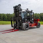
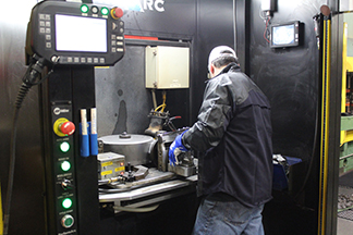
Taylor Machine Works Inc. has spent over 90 years building a reputation by engineering and producing exactly what its customers need. The company manufactures more than 85 models of powered industrial trucks, including forklifts and material handling equipment for a range of industries. “We manufactured roughly 750 pieces of rolling stock last year and 40 percent to 50 percent of that is highly customized,” said Matt Hillyer, director of engineering for Taylor, based in Louisville, Mississippi. “Our job is to build products that answer the customer’s needs.” Taylor’s “Big Red” forklifts, featuring the company’s distinctive “Big Red” logo, can handle material weighing up to 125,000 pounds — everything from palleted goods and empty shipping containers in waterfront shipyards to equipment encountering brutal hot and cold environments. Many of Taylor’s customers are small operations with from one to three pieces of equipment. Just one piece going out of service reduces production capacity by a large percentage. “Having high durability, high return on investment and low cost of ownership, those are all very imperative to our customers to make them successful,” said Hillyer. “It’s important for us not only to make custom products that are advanced in technology or state-of-the-art, but we also have to make products that are very simple, easy to work on and have lots of uptime. That’s what our customers are looking for.” Taylor employs some of the best welders in the business to meet those customer demands, but even great welders can’t overcome their tools’ limitations. When Taylor decided to try Bernard® semi-automatic MIG guns and Centerfire™ consumables, they discovered their talented team could take productivity up a few notches —and still gain the best quality. Making the change “Before we changed to Bernard welding products, we didn’t really know we were having a problem,” said Steve Nazary, quality assurance supervisor at Taylor. “When we started using Bernard [MIG guns and consumables], we found that they were much easier and more economical to use for our process.” Bernard semi-automatic MIG guns at 400, 500 and 600 amperages delivered more business benefits. Savings on service repair. “We can replace the liners, the tips, the nozzles” Nazary explained. “You can replace everything on a Bernard gun instead of throwing it away and buying a new one.” The previous guns Taylor used could not be repaired and components weren’t replaceable, resulting in increased costs for new purchases for their large manufacturing operation. Productivity-boosting ergonomics. “The Bernard MIG guns have a better handle on them,” Nazary said. “It fits your hand better. It has an easier trigger to pull. It doesn’t get as hot as the guns we were using before. We were using some handles before that got so hot, you couldn’t hold them anymore.” “Those twisty necks, as I call them, we can loosen them and change the angle to get in harder places. And you can reset them back straight, turn them on any angle. The employees love them.” Easier-to-use rotatable necks. Guns with multiple neck position options that are all easy to adjust let Taylor welders operate comfortably and precisely in more situations. Rather than turning the entire gun to get the right position to reach a weld joint, welders simply adjust just the neck of the gun to a better angle. Nazary added that it’s also easy to change necks on the Bernard MIG Guns to reach into tighter spaces. “We have multiple necks and they only take two or three seconds to swap them out,” he said. Centerfire™ consumables also proved to last much longer than products Taylor had used previously, reducing the need to change contact tips from multiple times per day to just once a day, on average. These consumables feature a non-threaded contact tip that is tapered at the base to seat easily in the gas diffuser. The result is better heat dissipation and a longer life. Plus, they are quick to change over. “We can change the Centerfire consumables with ease. We don’t have to have tools. You just twist the nozzle off, pull it off and pop another contact tip in and twist the nozzle back on,” said Nazary. Centerfire consumables also provide better gas flow for better welds and less rework. “With the other consumables that we were using, you would get different gas flows,” said Nazary. “With the Bernard products, we have consistent flow all the time.” “It’s absolutely imperative to make our products successful for the customer,” said Hillyer. “We also look to our suppliers, like Bernard to provide us with the best technology. They help us incorporate the right technology to make sure that we do have the most durable truck on the market.”
Implementing robotic welding can significantly improve a manufacturing operation’s productivity and weld quality, but what are the robotic welding basics you should know to be successful? From choosing the right welding wire to establishing proper tool center point (TCP), many variables play a role in optimizing robotic welding cells to produce the best results. Shaving even a few seconds from each weld cycle can save time and money. Minimizing the unplanned downtime for adjustments or repairs in the weld cell can also have a substantial impact on your bottom line. Success with robotic welding requires a well-researched plan. The more planning done upfront, the less time and money you could spend later making fixes and process improvements. Learning some basic tips for setting up a robotic weld cell can help to establish a repeatable and consistent process — so your operation can produce quality welds, reduce rework and maximize its investment. Proper weld settings for the application are based on factors including wire size and material thickness. Some welding power sources offer technology that allows welders to simply input the wire size and material thickness, and the machine will suggest recommended parameters for the application. Without this technology, finding the correct parameters can involve a bit of trial and error. Sometimes the robot manufacturer, welding power source manufacturer or system integrator can assist in choosing and testing specific materials to provide a starting point for the proper welding parameters. Utilize the experience of these partners to help you arrive at the best starting point and be prepared for the future. The choice of filler metal for a robotic welding system can significantly impact productivity, weld quality and the overall investment. Selecting the right wire for a robotic application is typically based on the material type and thickness, as well as the expected outcomes for the welded part. Welding equipment and filler metal manufacturers often offer charts to help you match a welding wire to your process needs. While solid wire has been the industry standard in robotic welding for many years, metal-cored wire is an alternative that can offer productivity and quality improvements in some applications, particularly in the manufacture of heavy equipment and automotive exhaust, chassis and wheels. However, be aware that each wire type offers pros and cons for certain applications, so it’s important to research the type that is best suited to your application. Robotic welding guns and consumables, including the nozzle, contact tip and gas diffuser, have a huge impact on performance in a robotic weld cell. The right combination can reduce unplanned downtime and improve overall efficiency of the cell. Be sure the welding gun is rated with enough duty cycle and amperage for the application. To avoid excessive wear and premature failure, the gun should not rub against any part of the system or another robot in applications where multiple robots are being used on the same tooling. Robotic welding systems typically operate at higher duty cycles than semi-automatic welding applications, and they may utilize transfer modes that are especially harsh on consumables. Consider using heavy-duty consumables that are more heat-resistant than standard-duty consumables. Chrome zirconium contact tips or tips specifically designed for pulsed welding processes are good options. In addition, ensure all consumables are properly installed and tightened. Improper or loose connections produce more electrical resistance and heat that causes faster consumable wear with premature failures. Another common failure in robotic welding is improper liner installation. Always follow the manufacturer’s directions for liner installation and cut length. A liner that is cut too short can cause premature failures of other consumables in the system. Make sure there is good cable grounding in the weld cell to help prevent potential problems as the cell ages. There are two cables running from the welding power source; one is attached to the wire feeder and the other is grounded to the tooling. Often, these cables are long and run from the shop floor to an elevated platform or through wire trays. The section of cable running up the robot or running to a positioner will constantly move — causing greater wear over time. Using a junction with high-flex ground cable at the base of the robot or the workpiece can save time and money in downtime and repair. With this solution, there is only a 6-foot section of cable to replace when it wears out, rather than replacing possibly 50 feet or more of ground cable that runs all the way back to the power source. However, keep in mind you should have as few breaks or junctions in the grounding cable as possible to maintain a better electrical connection. When mounting a ground cable to the welding workpiece, it can be helpful to use copper anti-seize lubricant, sometimes referred to as copper slop. This supports the transfer of electrical current and helps prevent the mounting point from fusing together or deteriorating over time. The lubricant can be useful in all areas where there may be grounding current running through pins or any other semi-permanent contact points. Proper cable management for the guns can also greatly extend cable life. The more any cable bends and flexes, the more wear and tear will occur — ultimately shortening cable life due to high heat and resistance. Work to minimize cable bending and flexing in your robotic process and tooling design. For repeatable and consistent weld quality, it’s critical to establish and maintain proper TCP. Welding operations can set their own standards for the acceptable amount of TCP drift, depending on the application and type of weld being made. When considering the tolerance of TCP variation, an acceptable starting point can be half the thickness of the wire diameter. Many robotic systems today can use touch-sensing features to monitor TCP and determine how far it has moved from the original programmed settings. If a gun is determined to be out of the acceptable TCP range, the gun neck can be removed and recalibrated offline to factory specifications with a neck straightening fixture. Some systems also provide the capability to adjust TCP automatically with the robot. A third option is to leave the gun in place and adjust the robot teaching to accommodate the modified TCP. This is the most time-consuming solution and, therefore, often not acceptable for the manufacturing operation. It also requires the need to reprogram the robot if new factory specifications for TCP or a new neck are ever put into place — which is why this method is typically the last resort. Set a schedule or standard for checking TCP, whether it’s every weld cycle, once a shift or even every time the torch goes through a reamer cycle. The length of time between checks is a matter of preference and weighing your priorities. It can be time-consuming to check every weld cycle, but this can save money in lost scrap and rework if a problem is found before welding occurs. The initial programming of the robot’s welding path can also involve much trial and error. When programming the path, consider the application, material type, welding process being used and gap size that must be filled. The weld quality and amount of spatter created are also impacted by the travel angle and whether it’s a pull or push weld. It can take time to dial in the correct path to achieve the desired quality. After setting the home positions in the robotic program, it’s recommended to have the robot move to perch points or ready-to-enter points that are safely away from any potential collision points, so the system can move quickly with air cut moves to and from these points. When programming the robot to move to a weld, it’s common to set the approach point just above the weld start location. Have the robot approach the start location at a slower and safer speed with the arc on. This approach position provides a good lead-in and typically won’t require adjustment unless the weld is relocated. Some robotic welding systems include technology that aids in setting the initial robot path. The robot’s welding location can play a role in premature failure of the gun. If the robot is welding with a lot of flex in the gun at a tight angle, this can cause it to fail much faster. Minimizing robot axes five and six during welding can help extend gun life by reducing wear. Proper part fit-up in the upstream process is critical to consistent weld quality and robot path programming. Inconsistent fit-up or large gaps between the parts lead to weld quality issues such as burn-through, poor penetration, porosity and others — resulting in additional unplanned downtime to deal with these problems. Large gaps between the parts may also require double weld passes, adding to cycle times. From wire and consumable selection to proper cable management and TCP, many variables play a role in weld quality and ultimately, the success of your robotic welding system. Careful planning at the start of the process and continued monitoring of these key factors helps optimize performance — so you can get the most from your robotic welding investment.
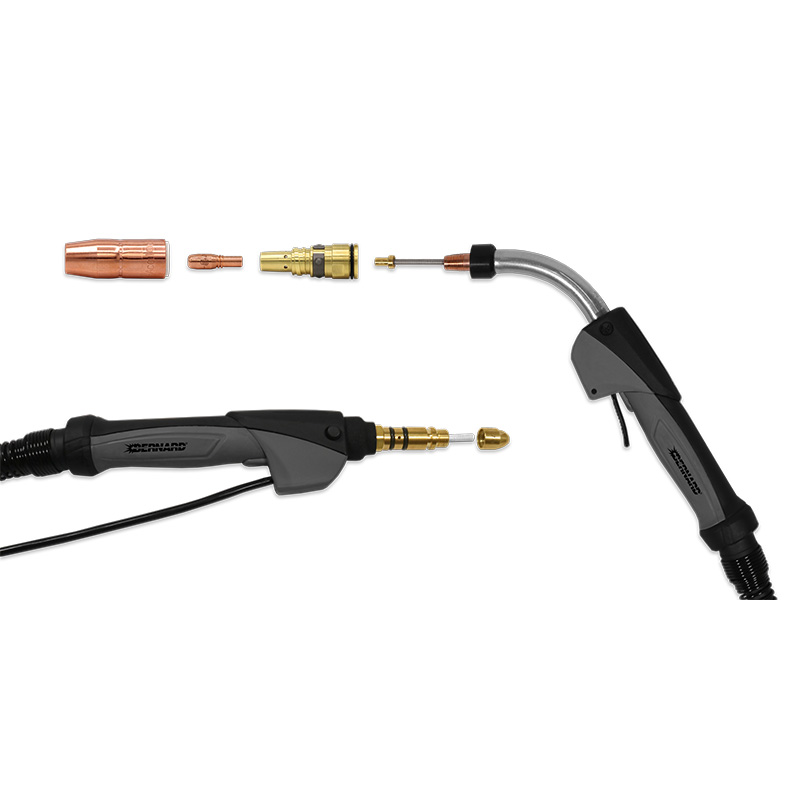
APPLETON, Wis. (February 6, 2019) — Miller Electric Mfg. LLC has introduced its new MDX™ series MIG guns. Designed with operator comfort in mind, these MIG guns feature a durable and ergonomic handle with a rubber overmolding for improved grip, while the addition of a ball and socket handle swivel reduces fatigue. AccuLock™ series consumables add to the performance of the gun, providing a flawless wire feed path. The front-loading liner locks in place (no need for set screws) and aligns concentrically with both the contact tip and power pin to optimize wire feeding. Error-proof liner trimming, with no measuring required, reduces burnbacks, bird-nesting and erratic arc caused by liners that are too short, minimizing downtime for troubleshooting or rework. The MDX series includes three models: MDX-100, MDX-250 and MDX-250 EZ-Select™. These guns are all compatible with Miller AccuLock MDX series consumables, and the MDX-250 and MDX-250 EZ-Select guns are also compatible with Bernard AccuLock S consumables. Both AccuLock series feature tapered connections between the contact tip, gas diffuser and neck to maximize electrical conductivity for longer product life. Coarse thread on the contact tips speeds replacement by mating easily with the gas diffuser and lessens the risk of cross-threading. Bernard® AccuLock S consumables are an excellent upgrade to increase durability and consumable life when welding with MDX-250 or MDX-250 EZ-Select guns in heavier industrial environments. They also simplify consumable inventory for operations using a mix of Miller MDX and Bernard MIG guns. Miller offers conversion parts to retrofit older style Miller MIGmatic M-Series guns with AccuLock MDX and AccuLock S consumables. M-Series consumables will not be compatible on the new MDX series MIG guns. The MDX series guns will be made available on multiple Miller power sources. The MDX-100 is rated at 100 amps. It pairs with the following: The MDX-250 contains increased copper in the cable, is pulse welding capable, and can be used with CV waveforms. It is compatible with the following: The MDX-250 EZ-Select gun features trigger program select that allows the user to select up to four weld programs by tapping the MIG gun trigger, saving time for walking to the machine to make changes. To help avoid errors, the gun features LED lights on the handle to indicate the weld program that is currently selected. It works with the following: For more information, visit MillerWelds.com/mdx.
January 8, 2019 Our product offering is regularly assessed to ensure focus on customer needs and opportunities to innovate our product portfolio, so we can continue to deliver sustainable value to our customers. Accordingly, due to low demand, the following products will be discontinued: Effective January 8, 2019, all legacy F-Gun MIG gun part numbers and all F-Gun series service parts will be discontinued and no longer available for sale. The following 600 amp Bernard® BTB semi-automatic air-cooled MIG gun models (with T series straight handles and locking triggers) are recommended replacement options:
January 25, 2019 To continue delivering sustainable value to our customers, we regularly assess our product offering to ensure focus on customer needs and opportunities to innovate our product portfolio. Accordingly, due to low demand, select Tregaskiss® nozzles will be discontinued. Effective March 1, 2019, all nozzles listed in the chart below will be discontinued as inventory depletes, and effective March 30, 2019, these nozzles will no longer be available for sale. Click here to download the above list in PDF format.
Tregaskiss Updates Robotic MIG Gun and Reamer Configurators
Tregaskiss Updates Robotic MIG Gun and Reamer Configurators

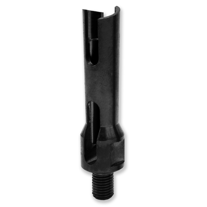
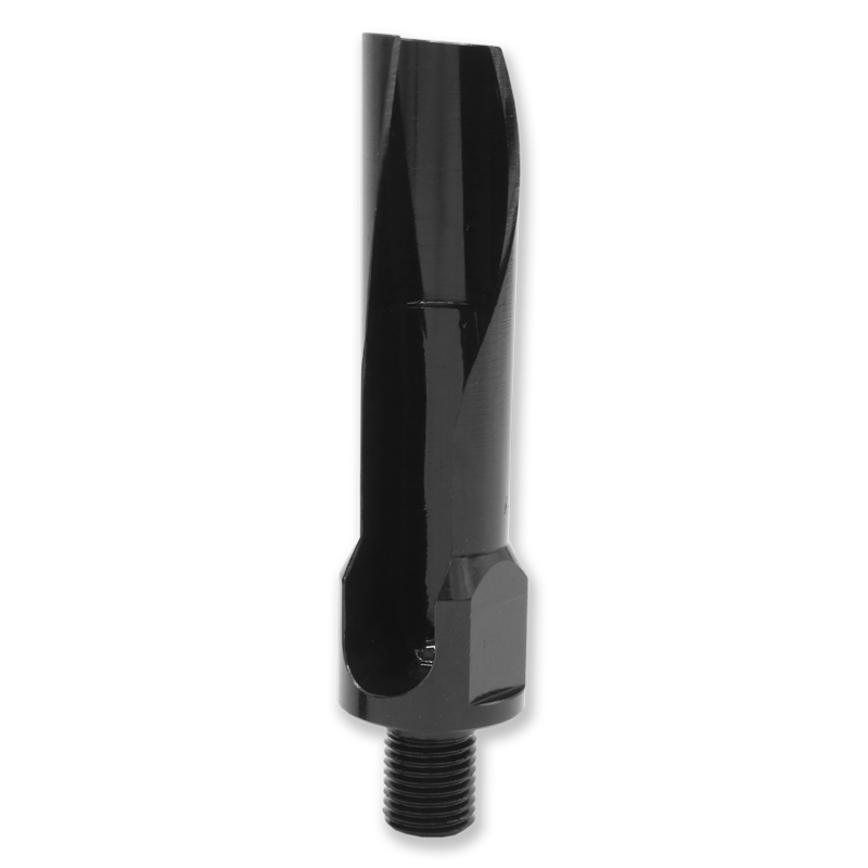
PRODUCT CHANGE – AccuLock S Power Pins for Miller Equipment
PRODUCT CHANGE –
New AccuLock S Power Pins for Miller Equipment
If your power pin has a large ID, please contact Customer Service to get the new AccuLock S Power Pin.
NEW (Shown Right) AccuLock S Power Pin Design
Torque to 10 ft-lbs / 120 in-lbs (13.5 Nm)Affected Part Numbers
2200137 Has been replaced by 2200206 and 2200207 in the AccuLock S consumables system as noted directly following 2200206 Replaces 2200137 for wire sizes 0.023″ (0.6 mm) – 5/64″ (2.0 mm) 2200207 Replaces 2200137 for wire sizes 3/32″ (2.4 mm) – 1/8″ (3.2 mm)
AccuLock S Consumables
PACKAGING CHANGE – 5-Gallon TOUGH GARD Anti-Spatter Liquid Pail
PACKAGING CHANGES –
5-Gallon TOUGH GARD Anti-Spatter Liquid PailAffected Part Numbers:

5-Gallon (18.9 L)
TOUGH GARD Anti-Spatter Liquid
Container
5-Gallon (18.9 L)
TOUGH GARD Anti-Spatter Liquid
ContainerCommon Problems With MIG Welding Consumables and How to Fix Them
Common Problems With MIG Welding Consumables and How to Fix Them

Making sense of welding nozzles

Avoiding contact tip downfalls
Pay close attention to the contact tip material to avoid premature failure. Consider these options:
Getting it straight about liners

Final considerations
Optimizing Shielding Gas Performance in MIG Welding
Optimizing Shielding Gas Performance in MIG Welding

This article was published in The WELDER. To read the entire story, please click here.
NEW PRODUCT – Conversion Diffusers for TOUGH LOCK Contact Tips
NEW PRODUCT —
Conversion Diffusers for TOUGH LOCK Contact TipsConversion Diffuser
Description


DISCONTINUED PRODUCT – BTB MIG Gun 500 amp B Series Handle Option
DISCONTINUED PRODUCT –
BTB MIG Gun 500 amp B Series Handle OptionBernard and Tregaskiss to Showcase Consumable and Gun Solutions at FABTECH 2019
Bernard and Tregaskiss to Showcase Consumable and Gun Solutions at FABTECH 2019

PRODUCT CHANGE – TOUGH GUN Reamer Cutter Blades
PRODUCT UPDATE —
TOUGH GUN Reamer Cutter BladesSummary of Color Changes and Affected Part Numbers


Affected Part Numbers – New Black Oxide Coating
Summary of Design Changes and Affected Part Numbers
Affected Part Numbers – New Single Flute Design (effective August 1, 2019)
5 Misconceptions About Robotic Welding Guns and Consumables
5 Misconceptions About Robotic Welding Guns and Consumables

This article has been published as a web-exclusive on thefabricator.com. To read the entire story, please click here.
DISCONTINUED PRODUCT – SURESTART Contact Tips

DISCONTINUED PRODUCTS – Tregaskiss SURESTART Contact Tips
Affected Part Number TOUGH LOCK® Direct Replacement 403-22-30 403-20-30-25 403-22-35 403-20-35-25 403-22-1.0 403-20-1.0-25 403-22-45 403-20-45-25 403-22-364 403-20-364-25 403-22-52 403-20-52-25 403-23-30 403-21-30-25
MIG Welding Basics: Techniques and Tips for Success
MIG Welding Basics: Techniques and Tips for Success
Proper ergonomics

Some ergonomic solutions that can improve safety and productivity include:
Proper work angle, travel angle and movement
Flat position
Horizontal position
Vertical position
Overhead position
Wire stickout and contact-tip-to-work distance
Welding travel speed
Final thoughts
2. Welding Handbook, 9th ed., Vol. 2, Welding Processes, Part 1. American Welding Society: Miami, Fla., p. 184. Implementing Robotic Welding: What to Know to Be Successful
Implementing Robotic Welding: What to Know to Be Successful

Budgeting and ROI
Effective training

Avoid common mistakes

Final thoughts
Preventive Maintenance for Reamers, Accessories and Other Peripherals
Preventive Maintenance for Reamers, Accessories and Other Peripherals
PM tips for reamers and accessories

Preventive Maintenance Checklist

PM tips for wire cutters
The value of peripherals
MIG Welding Consumables Reduce Wire Feeding Issues and Downtime
MIG Welding Consumables Reduce Wire Feeding Issues and Downtime

The cost of poor consumable performance
Error-proof liner replacement
Optimize wire feeding
Maximize performance and life
Reduce wire-feeding and weld quality issues
Bernard Updates Online Configurators with Expanded Capabilities
Bernard Updates Online Configurators with Expanded Capabilities
MIG Gun Consumable System Simplifies Installation, Offers Flawless Wire Feeding
MIG Gun Consumable System Simplifies Installation, Offers Flawless Wire Feeding
About the MIG Gun Consumable System

Robotic Welding Troubleshooting FAQs
Robotic Welding Troubleshooting FAQs
Q: What are causes of poor consumable performance?
Q: What causes poor wire feeding?

Q: Why is the cable prematurely failing?
Proper cable length is also important. A cable that is too short or too long can be stretched beyond capacity or be prone to kinking.Q: Why is there a problem with tool center point (TCP)?
Q: How do I fix poorly performing peripherals?

Correcting common problems
Taylor Forklift Operation Reduces Downtime, Costs with Bernard
Taylor Forklift Operation Reduces Downtime, Costs with Bernard


According to Taylor, sometimes it takes trying a new technology to realize what you’ve been missing. That was the case with the Bernard products — the manufacturers of the Big Red material handling machines had a business epiphany.

Helping Taylor Machine Works serve customers
All the advantages found by using Bernard semi-automatic MIG guns and Centerfire consumables align perfectly with Taylor’s commitment to quality and meeting the customer needs. And the reliability of the products fits well with the company’s slogan: “Depend on Red.”7 Tips for Implementing a Robotic Welding Cell
7 Tips for Implementing a Robotic Welding Cell

Tip No. 1: Use proper weld settings
Tip No. 2: Choose the right wire

Tip No. 3: Consider the gun and consumables
Tip No. 4: Reduce cable wear
Tip No. 5: Establish TCP

Tip No. 6: Program the robot path
Tip No. 7: Ensure proper fit-up
Closing
AccuLock Consumables With Miller MDX Guns Offer Flawless Wire Feeding
AccuLock Consumables With Miller MDX Guns Offer Flawless Wire Feeding
Gun compatibility and capabilities
DISCONTINUED PRODUCT – Legacy F-Gun MIG Guns and Service Parts
DISCONTINUED PRODUCTS –
Legacy F-Gun MIG GunsLegacy F-Gun™ MIG Guns
Affected Part Numbers
Part Number Description 4610 F-Gun MIG Gun, 10 ft 4615 F-Gun MIG Gun, 15 ft 4610E F-Gun MIG Gun, 10 ft, Euro 4615E F-Gun MIG Gun, 15 ft, Euro 4610M F-Gun MIG Gun, 10 ft, Miller® 4615M F-Gun MIG Gun, 15 ft, Miller 4610L F-Gun MIG Gun, 10 ft, Lincoln® 4615L F-Gun MIG Gun, 15 ft, Lincoln 4610T F-Gun MIG Gun, 10 ft, Tweco® 4615T F-Gun MIG Gun, 15 ft, Tweco 408 Handle, F-Gun Series 4627 Neck, F-Gun Series 429 Trigger, F-Gun Series
Replacement Options
Legacy F-Gun MIG Gun Part Number Replacement BTB MIG Gun Part Number 4610 Q6010NU3LBC 4615 Q6015NU3LBC 4610M Q6010NU3LMC 4615M Q6015NU3LMC 4610L Q6010NU3LLC 4615L Q6015NU3LLC 4610T Q6010NU3LTC 4615T Q6015NU3LTC DISCONTINUED PRODUCT – Select Nozzles
DISCONTINUED PRODUCTS –
Select Tregaskiss NozzlesPart Number Description Substitution Notes Reamer Change 401-11-62 Nozzle, TIGHT RADIUS™, 5/8″ bore, 1/8″ recess — TCP change – Please contact Customer Service at 1.855.MIGWELD (644.9353) Yes 401-12-50 Nozzle, TIGHT RADIUS, 1/2″ bore, flush — TCP change – Please contact Customer Service at 1.855.MIGWELD (644.9353) Yes 401-13-62 Nozzle, TIGHT RADIUS, 5/8″ bore, 1/8″ stick out — TCP change – Please contact Customer Service at 1.855-MIGWELD (644.9353) Yes 401-19-62 Nozzle, 5/8″ bore, 1/4″ recess, brass 401-14-62 401-14-62 is 1/8″ recess, copper No 401-21 Nozzle, Flux-Core, 1/4″ recess — Discontinued – No replacement No 401-41-75 Nozzle, 3/4″ bore, 1/8″ recess 401-7-75 or 401-14-62 Move to slip-on 401-7-75 with new 404-32 retaining head (v-block change); or Move to 5/8″ bore (copper) 401-14-62 (no retaining head, but cutter change) Yes
(401-7-75: v-block;
401-14-62: RCT-01)401-43-50 Nozzle, 1/2 bore, 1/4″ recess 401-47-51 401-47-51 is 1/8″ recess, and different profile No 401-44-501 Nozzle, 1/2″ bore, 1/4″ stick out 401-44-50 401-44-50 is bottleneck style, not tapered No 401-45-38 Nozzle, 3/8″ bore, flush, old thread 401-4-38 Must use 404-52 or 404-53 retaining head No
(no 3/8 cutter)401-45-50 Nozzle, 1/2″ bore, 1/8″ recess, old thread 401-47-51 Must use 404-52 or 404-53 retaining head No 401-45-62 Nozzle, 5/8″ bore, 1/8″ recess, old thread 401-43-62 Must use 404-52 or 404-53 retaining head No 401-46-38 Nozzle, 3/8″ bore, 1/8″ recess, old thread 401-42-38 Must use 404-52 or 404-53 retaining head No 401-46-62 Nozzle, 5/8″ bore, 1/4″ recess, old thread 401-43-62 401-46-62 is 1/8″ recess; Must use 404-52 or 404-53 retaining head No 401-47-50 Nozzle, 1/2″ bore, 1/8″ recess, old thread 401-47-51 Must use 404-52 or 404-53 retaining head No 401-52-62 Nozzle, 5/8″ bore, 1/4″ recess 401-14-62 401-14-62 is 1/8″ recess No 401-54-50 Nozzle, TOUGH ACCESS™, 1/8″ recess 401-55-50 401-55-50 is flush No 401-55-62 Nozzle, TOUGH ACCESS, flush 401-54-62 or 401-56-62 401-54-62 is 1/8″ recess; 401-56-62 is 1/8″ stick out No 401-68-62 Nozzle, 5/8″ bore, flush, copper 401-51-62 Copper to brass No 401-92-62 Nozzle, 5/8″ bore, 1/4″ recess, brass 401-91-62 401-91-62 is 1/8″ recess No 401-9-75 Nozzle, 3/4″ bore, 1/2″ recess 401-5-75 401-5-75 is 1/4″ recess No 451-4-38 Nozzle, 3/8″ bore, 3/16″ recess 451-6-50 451-6-50 is 1/2″ bore No 451-45-50 Nozzle, High Access, water-cooled (semi-auto) 451-6-50 451-6-50 is tapered style, not bottleneck No 451-5-75 Nozzle, 3/4″ bore, 1/4″ recess, water-cooled (semi-auto) 451-5-62 451-5-62 is 5/8″ bore No 451-81-62 Nozzle, 5/8″ bore, 1/8″ stick out, water-cooled (semi-auto) 451-61-62 451-61-62 is flush No 451-87-62 Nozzle, 5/8″ bore, 3/16″ stick out, water-cooled (semi-auto) 451-61-62 451-61-62 is flush No
![]()