NEW PRODUCT – AccuLock S Consumables
November 1, 2018
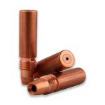
Bernard is proud to introduce new AccuLock™ S consumables, a system designed to address liner trim length errors and erratic wire feeding.
Important Note: Most components of the AccuLock S consumables family are currently available. The complete offering will be coming soon.
The AccuLock S liner is locked and concentrically aligned to both the contact tip and the power pin without the use of fasteners, which provides a flawless wire-feed path that guarantees smooth, uninterrupted delivery of the wire to the weld puddle. Plus, the liner replacement process has been error-proofed so you can trim your liner accurately and easily every time, with no measuring.
The AccuLock S consumables system requires all AccuLock components: contact tip, diffuser, nozzle, liner, neck insulator, power pin and power pin cap.
Key features of Bernard AccuLock S Consumables

MIG welding, like any other process, takes practice to refine your skills. For those newer to it, building some basic knowledge can take your MIG welding operation to the next level. Or if you’ve been welding for a while, it never hurts to have a refresher. Consider these frequently asked questions, along with their answers, as welding tips to guide you. The welding wire size and type determines the drive roll to obtain smooth, consistent wire feeding. There are three common choices: V-knurled, U-groove and V-groove. MIG welding wires vary in their characteristics and welding parameters. Always check the wire’s spec or data sheet to determine what amperage, voltage and wire feed speed the filler metal manufacturer recommends. Spec sheets are typically shipped with the welding wire, or you can download them from the filler metal manufacturer’s website. These sheets also provide shielding gas requirements, as well as contact-to-work distance (CTWD) and welding wire extension or stickout recommendations. Contact tip recess, or the position of the contact tip within the MIG welding nozzle, depends on the welding mode, welding wire, application and shielding gas you are using. Generally, as the current increases, the contact tip recess should also increase. Here are some recommendations. The shielding gas you choose depends on the wire and the application. CO2 provides good penetration when welding thicker materials, and you can use it on thinner materials since it tends to run cooler, which decreases the risk of burn-through. For even more weld penetration and high productivity, use a 75 percent argon/25 percent CO2 gas mix. This combination also produces less spatter than CO2 so there is less post-weld cleanup. For all positions, it is best to keep the welding wire directed toward the leading edge of the weld puddle. If you are welding out of position (vertical, horizontal or overhead), keeping the weld puddle small provides the best control. Also use the smallest wire diameter that will still fill the weld joint sufficiently.
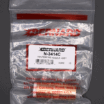
November 1, 2018 Customers may notice that some Bernard® parts and consumables are arriving in different bags. We transitioned to a newly designed Bernard branded white bag design. In addition to changing the artwork layout and color of the bags, the overall usability has also been improved. These new white bags offer a clear window on the printed side of the bag to make visual product identification easier. To increase the hanging capacity of the bags, we’ve added a second hanging hole on our larger bags and a new double-sealed header on all bag sizes. The sombrero shaped hanging holes provide compatibility with a wider variety of hook sizes and shapes.
November 1, 2018 Customers may notice that some Tregaskiss® parts and consumables are arriving in different bags. We transitioned from a black bag design to a white bag design. This new white bag design has a clear window on the back side of the bag to help make visual product identification easier, and the durability and hanging holes remain the same as our previous black bag packaging.
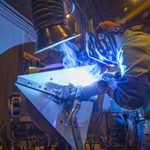
For structural applications, some contractors have made the switch from stick welding to self-shielded flux-cored welding to increase productivity and give themselves a competitive edge. Self-shielded flux-cored welding offers much greater travel speeds and deposition rates compared to stick welding, while also eliminating the frequent stopping and starting required to change out stick electrodes. For contractors considering this conversion, there are some key factors to keep in mind to help choose the right self-shielded flux-cored welding gun for the job — and to use and maintain it properly. Gun options such as heat shields, configurable necks and adjustable cable lengths can help improve weld quality, efficiency and operator comfort in self-shielded flux-cored applications. Self-shielded flux-cored welding is becoming more common on jobsites for several reasons. In addition to the greater productivity and deposition rates of the process, it also doesn’t require a shielding gas to protect the weld pool, eliminating the hassle and cost of buying and storing gas containers on the jobsite. Not using shielding gas also eliminates the need to set up tents or wind shields to protect the weld from the elements and the need to use specialty nozzles to control gas flow as is common with a gas-shielded flux-cored process. Some training may be required for welders who are used to the stick process. The different ergonomics of the self-shielded flux-cored gun compared to the stick electrode holder require approaching the weld from different angles and using different travel angles and pressure. When stick welding, the operator typically begins with the electrode (and therefore his or her body) farther from the weld. As the rod shortens during welding, the welder gets physically closer to the weld, applying pressure to the stick electrode as it melts into the weld pool. In self-shielded flux-cored welding, the welder stays in the same spot, maintaining a consistent distance between the contact tip and the weld pool. The proper contact-tip-to-work distance depends on the application, but at least 1/2 inch is a good rule of thumb. Self-shielded flux-cored welding can be prone to slag inclusions if proper technique isn’t followed. Regularly inspect the contact tip to ensure it’s free from spatter and debris buildup, which helps ensure smooth wire feeding. Properly clean the weld between passes. Welding guns for self-shielded flux-cored applications are available in various configurations. Choosing the right gun can help contractors tailor it to their specific needs and applications. Consider these features: Heat shield: One of the most common features on self-shielded flux-cored welding guns is a hand guard or heat shield, which is available in different sizes. In applications that require access to a corner joint, choosing a smaller guard increases maneuverability and provides more access. When welders need to run at a higher voltage and deposit more filler metal into the weld, using a larger guard helps deflect the higher heat. Neck lengths and bends: Gun necks are available in varying lengths and bend angles. A slimmer neck provides a better view of the weld pool and improved access to tight areas, for example. A shorter neck typically provides more control compared to a longer neck. Lightweight, rotatable necks can also reduce operator fatigue and improve weld visibility. Replaceable or fixed cable liner: Some self-shielded flux-cored gun models are available with either a replaceable cable liner or a fixed cable liner. A replaceable cable liner provides benefits in harsh and demanding environments, since self-shielded flux-cored welding can be hard on equipment and consumables. Replaceable power cable liners provide quick and easy cable maintenance and can extend product life since welders can change out components that experience high levels of wear. In addition, choosing a replaceable cable liner with internal trigger leads means there is no external trigger cord that can catch on surrounding objects. Conversely, fixed cable liners tend to be larger, which can be an issue when welding in corners or tight spaces. Dual schedule switch: A self-shielded flux-cored gun with an optional dual schedule switch allows for wire speed adjustment while welding. In some guns, this switch is integrated into the handle to keep it protected from spatter. The ability to toggle between weld parameters easily — without having to stop welding and change settings — saves time and improves productivity. There are ways to extend the life of the gun and consumables. The necessary frequency of gun and consumable maintenance depends on the application and the welding environment. Conduct routine checks to ensure front-end consumables are in good shape and all connections are tight. This helps keep heat resistance low and ensures proper electrical conductivity so the gun and consumables last longer. Consider using a rotatable gun neck with a collet-style connection, which makes it easier to drop the neck in and tighten it. Consumables that use compression fittings also provide more efficient energy transfer and less overheating to help extend product life. Be sure to keep the contact tip clear of spatter buildup and inspect the tip for signs of wear or keyholing, and also inspect the cable for any damage or nicks. While the self-shielded flux-cored process is capable of welding material with dirt, oil or mill scale, remember that better surface preparation delivers better results in any welding application. Properly cleaning the base material will help produce better welds. Because flux-cored welding produces a slag and spatter, there is also a need to remove the slag between passes and for post-weld cleaning. Be aware that travel angles beyond 20 or 25 degrees can increase spatter and arc instability. With flux-cored welding, it’s recommended to use a drag technique with a travel angle of 5 to 15 degrees. As more contractors look for ways to increase productivity and efficiency on the jobsite, the use of self-shielded flux-cored welding grows. Choosing a welding wire designed to improve a weld’s chemical composition or deposition rates can provide even more benefits. The self-shielded flux-cored process can be a good alternative to stick welding in many outdoor applications that boosts productivity and reduces costs.
Is your robotic welding operation costing time and money for problems like burnbacks, premature contact tip wear, loss of tool center point (TCP) or other issues? These common failures in robotic welding can be costly, resulting in downtime and unplanned part replacement. Even issues that seem minor, such as the wire sticking to the contact tip and forcing tip replacement, can cost thousands of dollars per day when you consider lost consumables, cell downtime and labor costs for changeover. Beyond the time and money spent on minor issues, there’s also the risk of catastrophic failure that could short out the robot or damage system electronics — potentially costing tens of thousands of dollars. Avoiding common failures is often a matter of proper weld cell setup and robot maintenance, in addition to following some best practices for consumable installation. Operator training is also critical in preventing common failures in robotic welding. One of the most common failures in a robotic weld cell is burnback and premature contact tip wear. The top cause of burnback is an improperly trimmed gun liner. When a liner is too short, it won’t seat in the retaining head properly, causing burnback. To avoid this problem, follow the manufacturer’s recommendations for proper liner trimming. It’s also helpful to choose a high-quality liner designed for accurate liner trimming and installation. Burnback is one cause of premature contact tip wear, but wear can also result from other factors. Using low-quality wire with a lot of cast can be another cause, as it quickly wears out the contact tip compared to using a better-quality, straighter wire. Drive rolls that are too tight can also cause wire cast issues that wear the contact tip faster. Improper welding parameters — such as welding too hot or too cold — can also wear contact tips prematurely and force more frequent changeout. Adjust parameters accordingly to minimize this problem. The main cause of broken cutter blades in robotic welding is incorrect positioning or too much angle of the robotic MIG gun nozzle as it enters the reamer for cleaning. For example, if the depth of the Z axis is too deep, the torch will go in too far and may cause the reamer blades to break. To prevent this, the nozzle should be concentric to the cutting blade. Use an angle finder app on your smartphone or tablet to ensure the positioning is straight up and down on the X and Y positions. Also, be sure the insertion depth on the nozzle goes past the gas holes on the diffuser. Drag marks on the diffuser or contact tip are signs of wear that mean the nozzle is not concentric to the reamer blade. Proper setup and positioning also helps ensure consistent coverage of anti-spatter spray on the nozzle. Broken cutter blades can also result from excessive spatter in the nozzle, which can be caused by poor spraying setup, incorrect weld parameters or incorrect torch angle. Spatter sticks to spatter and as the buildup grows, it can break the cutter blade as it tries to enter the nozzle. Keep in mind that you may need to ream and spray more frequently depending on the application and the material being welded to avoid some of these issues. Problems with the contact tip, nozzle, reamer and excessive spatter can also result when there is poor grounding in the weld cell. Regularly inspect all cables for damage and be sure the ground cables are securely connected. When TCP is lost in a robotic weld cell, one common cause is improperly installed consumables. A cross-threaded consumable will angle the contact tip where it meets the retaining head, causing the tip to bend and disrupting TCP. Be sure to tighten consumables to the manufacturer’s torque specifications. The general rule of thumb is one quarter turn past finger tight. A worn clutch can also cause loss of TCP. The clutch system helps prevent damage to the robot or gooseneck during tooling collisions. After repeated incidents, the clutch may allow a few degrees of movement in either direction, which throws off TCP. Consider using a neck inspection fixture, which tests and adjusts the tolerance of a robotic MIG gun’s neck to the TCP so you can readjust it after an impact or after bending due to routine maintenance. In a robotic weld cell, the disc functions as a buffer between the mount and the robot arm. It’s designed to be sacrificial; if the torch, mount or robot arm collide, the disc will absorb the bulk of the impact. However, the disc can be broken when it’s hit hard enough by the neck or torch mount, so replace it if damaged. Set the robot path correctly to avoid neck collisions. Overtightening the screws can also break or crack the disc and cause it to fail. Discs have torque specifications from the manufacturer. Use those specifications to prevent overtightening and reduce the risk of cracking. The specification sheet also describes the order in which the screws on the disc should be tightened. Robotic weld cell failures can also be caused by programming errors. If the robot’s path to the tooling is programmed incorrectly, the arm can come into contact with the tooling or the weld cell wall. The torch rubbing on the cell wall can create holes in the cable. In addition, if the neck frequently hits the tooling, this can bend the neck or cause the disc to break. To prevent these issues, program the robot so the arm is clear of the tooling and doesn’t encounter the tooling or the wall. Preventive maintenance is key to keeping a robotic welding system and its components performing optimally — and extending consumable life. Regularly check all cables to make sure they are secure, free of damage and not rubbing anything. Establish and follow a schedule for liner changeover. The required frequency of liner changeover depends on what type of filler metal is being used, what material is being welded and shop conditions. A shop that is very dusty means liners will clog faster, for example. Consult the manufacturer’s maintenance recommendations and follow a preventive maintenance checklist to ensure all the system’s components and parts remain in good working order. Using high-quality robotic MIG guns and consumables also helps prevent problems that can arise in the weld cell. Taking steps to avoid common failures in the robotic weld cell allows your operation to improve productivity, reduce consumable costs and ensure consistent part quality.
September 12, 2018 To continue delivering sustainable value to our customers, we regularly assess our product offering to ensure focus on customer needs and opportunities to innovate our product portfolio. Accordingly, due to low demand, the following products will be discontinued: Effective September 30, 2018, all standard and special Tandem MIG guns and necks will be discontinued and no longer available for sale. All service parts for Tandem torches will be available for sale until December 31, 2018, at which time all service parts for Tandem torches will be discontinued. Click here for a list of affected part numbers.
September 12, 2018 To continue delivering sustainable value to our customers, we regularly assess our product offering to ensure focus on customer needs and opportunities to innovate our product portfolio. Accordingly, due to low demand, the following products will be discontinued: Effective December 31, 2018, all service parts for Tregaskiss® quick-change water-cooled (QCWC) and Tregaskiss keyed water-cooled (KWC) robotic MIG guns (discontinued October 1, 2008) will be discontinued and no longer available for sale. Click here for a list of affected part numbers. Note: Availability and list prices of replacement parts for the affected products are subject to change without notice.
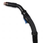
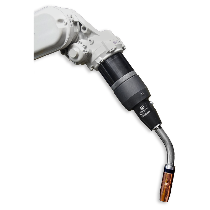
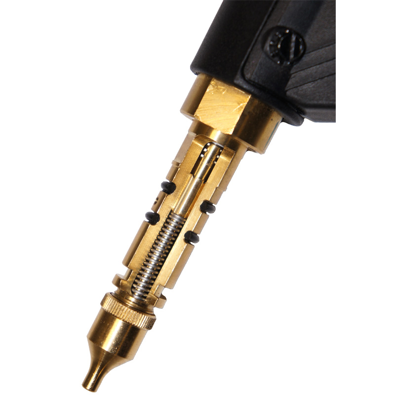
WINDSOR, Ontario. September 11, 2018 — Tregaskiss has expanded its TOUGH GUN® TA3 robotic air-cooled MIG gun offering to include configurations for additional through-arm style robot models in the marketplace. These include: In addition to being fully customizable according to robot make and model, most TOUGH GUN TA3 robotic MIG guns can be configured with the desired solid or clutch mount/wire brake/air blast combinations, neck, nozzles, contact tips and more at Tregaskiss.com/ConfigureMyGun. The guns have been designed with precision and reliability in mind and feature the unique low-stress robotic (LSR) unicable, which incorporates a rotating power connection for stress-free rotation that helps extend the life of the cable. A specially engineered neck clamp improves the consistency and durability of the clamping force, while a wide selection of standard necks expands the tool center point (TCP) options and variety of working envelopes. The TOUGH GUN TA3 robotic air-cooled MIG guns are compatible with Tregaskiss® consumables and with the QUICK LOAD™ liner AutoLength™ system — a system that helps rectify wire feeding and quality issues associated with incorrect liner length. Housed inside the power pin, the spring-loaded module applies constant forward pressure on the liner, keeping it seated properly in the retaining head and allowing up to one-inch forgiveness if the liner is too short.
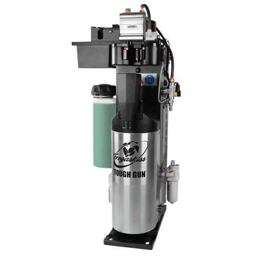
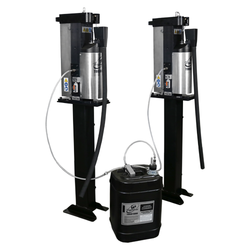
When using anti-spatter liquid in a robotic weld cell, there are steps you can take to optimize the application of the spray. The addition of an anti-spatter sprayer to a nozzle cleaning station helps ensure delivery of consistent amounts of anti-spatter liquid, leading to longer consumable life, better weld quality and higher productivity. You can also add an anti-spatter multi-feed system to help lower costs, minimize downtime and increase safety. These systems eliminate the need to refill spray reservoirs frequently by feeding up to 10 reamers from a single 5- or 55-gallon drum of anti-spatter liquid. Position the robotic MIG Gun and front-end consumables correctly. Aligning these in the right location for the ream cycle and anti-spatter liquid application helps apply the liquid uniformly. Always follow the manufacturer’s instructions for proper setup based on the nozzle bore size. If the sprayer is too far away from the nozzle, it will not provide adequate coverage to prevent spatter buildup. If the nozzle and sprayer are too close, too much spray may saturate the nozzle insulator, which can lead to premature failure. Spray for about a half-second. If you need to spray longer, it usually means the sprayer is too far away. Never spray the liquid for three or more seconds, as it can harm the consumables, cause residue buildup in the weld cell (and with it slippery surfaces) and may damage power sources by adversely affecting the electrical circuits. Use a spray containment unit. This 3- to 4-inch unit fits over the spray head on the anti-spatter liquid sprayer to capture excess anti-spatter liquid. After the spatter has been cleared from the nozzle during the reaming cycle, the nozzle docks on the spray containment unit. An opening at the top of the cylinder allows the anti-spatter liquid to spray onto the nozzle while an O-ring seals the nozzle in place; only the outside edge and inside of the nozzle are sprayed. To care for a spray containment unit, routinely remove any spatter or debris from the bottom and clear the screen or filter inside the unit of contaminants using clean, compressed air.
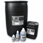
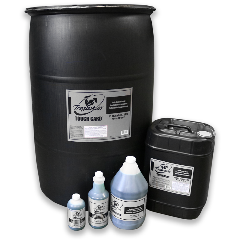
Having the right products for your welding application impacts quality and productivity. Anti-spatter liquid is no exception. When selecting an anti-spatter liquid for a robotic welding application, be certain that it offers the following attributes: • Uniform coverage to protect the entire nozzle A water-soluble compound, like Tregaskiss® TOUGH GARD® anti-spatter liquid, is a popular option. This liquid is non-toxic and eco-friendly, helping companies to improve employee safety and provide a cleaner work environment. Oil-based anti-spatter liquid is also available in the marketplace, but is generally less desirable to use because it is more difficult to clean up if it settles on fixtures or other parts in the weld cell. Oil-based anti-spatter liquid is not always compatible with all nozzle cleaning stations, and it can clog this equipment. Even though the more popular water-based anti-spatter compound is non-toxic, you should always take care when handling and using it. This article is the second in a three-part series focused on the use and benefits of anti-spatter liquid. Read article one, Spatter in Welding: Should You Consider Anti-Spatter Liquid? and article three, Anti-Spatter Sprayer: How to See the Best Results
Are you losing money and arc-on time for excessive contact tip changeovers? Anti-spatter liquid may be an option to help. This compound protects the front-end consumables on your robotic MIG gun from spatter accumulation, reducing downtime for tip replacements and helping to prevent shielding gas flow restrictions that could lead to porosity. This liquid also: • Prolongs the life of the nozzle, contact tips and gas diffuser Although it resembles water in its consistency, anti-spatter liquid (when applied correctly and in the appropriate volume) will not drip like water. Rather, it creates a barrier between the nozzle and any spatter generated during the welding process. The spatter easily falls off when the nozzle cleaning station or reamer performs the reaming cycle, leaving the nozzle and other front-end consumables clean. Note, you must reapply the compound frequently to help maintain that barrier. Constant-voltage (CV) applications and those utilizing solid wire and/or the welding of galvanized steel tend to produce high levels of spatter and often benefit the most from the use of anti-spatter liquid. Anti-spatter liquid also benefits high-volume, high-production operations where the goal is to minimize potential weld quality issues, extend consumable life and reduce downtime. Its application can easily be programmed so that it is sprayed onto the consumables after each ream cycle, during routine pauses in production for part changeover. Learn about TOUGH GARD® anti-spatter liquid. This article is the first in a three-part series focused on the use and benefits of anti-spatter liquid. Read article two, How to Select and Use Anti-Spatter Liquid, and article three, Anti-Spatter Sprayer: How to See the Best Results.
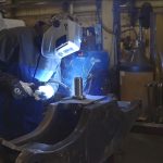
Taylor Machine Works saves money and improves performance by welding its forklifts with Bernard MIG guns. All Bernard MIG gun parts are replaceable, and the necks adjust to fit tight joints. “You can put different necks on the guns. Those twisty necks, I call them. We can loosen them use them and change the angle to get in tighter places. The employees they love them. Bernard guns are very helpful to us and our welding process” raves Craig Callahan, Quality Control Welding Inspector for Taylor Machine Works. “When we first went to a Bernard gun, I had one man who didn’t change a tip for 27 days. They usually we’re changing tips, nozzle and diffusers multiple times a day. Now they only have to change the tips once a day”, says Steve Nazary, Quality Assurance Supervisor for Taylor Machine Works, since converting to Centerfire™ consumables. Bernard MIG welding consumables help Taylor Machine Works save time by reducing contact tip changeover in its forklift welding operations.
Optimizing the robotic weld cell helps improve productivity, allowing a manufacturing facility to save time and money. It can be especially beneficial in applications that use pulsed gas metal arc welding (GMAW-P), a process that results in rapid wear to the welding gun’s front-end consumables. While the choice of contact tip for the GMAW gun may seem like a small factor in the entire operation, consider how much time it takes for an operator to enter the weld cell and change the contact tip — and how many times per day the tip is changed in most robotic welding operations. For example, copper contact tips are changed on average four times per shift. In a three-shift operation averaging 10 minutes per tip change, that equates to spending two hours per day changing contact tips. What else could a welding operator be doing with this time to create value in the manufacturing operation? There are contact tip innovations that help significantly reduce the downtime spent on changeover — time that can be spent on other tasks in the operation, such as increasing production up-time. In addition, when the operator spends less time in the weld cell, it reduces the potential of health and safety incidents and the possibility of weld quality issues through altering weld settings and parameters such as tool center point. For these reasons, it’s important to consider the total cost of ownership when selecting the right contact tip for a robotic welding operation. As more manufacturing applications use thinner, lighter and more corrosion-resistant materials to meet industry demands, this increases the use of GMAW-P processes, which offer benefits for welding thin-gauge materials. Pulsed waveform technology continues to develop, offering faster travel speeds, reduced spatter levels and high weld quality in many robotic applications. However, pulsed processes typically require a higher frequency of contact tip changeover due to the energy of the process. Faster contact tip deterioration is caused by peaks in pulse waveforms where the energy/heat is five times greater than in traditional constant voltage (CV) GMAW. Because of this, arc erosion is a common failure for contact tips in GMAW-P. Contact tip failure increases an operation’s costs, due to the increased frequency of downtime related to tip changeover. A new contact tip design has resulted in tips with improved resistance to arc erosion that last much longer in pulsed welding. Contact tips made from copper or copper chrome zirconium are commonly used in many welding applications. However, adoption of a GMAW-P process can double contact tip replacement frequency and related downtime when using copper or chrome zirconium tips. A new innovative technology on the market today can significantly extend the time between contact tip changeover, thanks to a combination of proprietary materials and tip design. HDP contact tips from Tregaskiss last more than 10 times longer than copper or chrome zirconium tips, allowing operations to go from changing contact tips two to four times each shift to only changing the tips once every third shift or longer. HDP contact tips are engineered to resist wear better than other materials and designs previously used for contact tips, providing increased resistance to arc erosion in pulsed welding, as well as spray transfer and CV GMAW. The precise fit between the tip and the wire also results in good arc stability to help produce high-quality welds, and because the degradation of welding current from the power source to the contact tip is reduced, it provides a truer representation of the pulsed waveform program. The tips currently come in .035, .040 and .045 sizes and can be used with standard nozzles and TOUGH LOCK® retaining heads as well as with air-cooled guns or water-cooled guns. HDP contact tips can be used with Tregaskiss guns, as well as guns from other MIG welding gun manufacturers. Because the tip bore is sized so tightly to the welding wire, it’s best to use the HDP Contact Tip with good-quality welding wire that has a large cast. A high-quality wire typically has a consistent wire diameter, which promotes better feeding and optimized performance. Typically, operations conduct contact tip changeovers on a preventive maintenance schedule to avoid unplanned downtime in the manufacturing process. The necessary frequency of contact tip changeover varies based on many factors including application, wire type and quality, waveform and base material. Many robotic welding operations have 100 welding arcs or more and run three shifts per day. In robotic welding operations, copper tips are changed on average four times per shift — or 12 times per day. Chrome zirconium tips are changed about half as often, or six times per day. A scheduled contact tip change typically takes 10 to 15 minutes to complete. Compare this to real-world results from several manufacturing operations using HDP contact tips. For example, one manufacturing operation converted to HDP contact tips in a solid wire GMAW-P application. The operation produces 600 parts per shift, and the previous chrome zirconium contact tip required changeover every 60 to 80 parts — or about 10 times per shift. In the company’s trial, one HDP contact tip was still running after 2,500 parts under the same parameters. Another manufacturing operation running a standard GMAW process tried HDP contact tips on a line of 18 robots. Where previous contact tip usage for the operation was 216 per day — or about 1,500 tips per week — one HDP contact tip lasted an entire week on each cell, totaling 18 tips per week. In addition to the significant productivity gains the new contact tip design provides, there are other benefits for arc stability, productivity and operator safety. Reduced frequency in contact tip changeover not only increases throughput while saving time and money due to downtime, it also reduces the risk of safety incidents, since every time an operator enters the weld cell it increases the risk of injury. Also, each time someone touches the welding gun, there is the risk putting it out of alignment. The less frequently an operator must enter the cell, the less chance there is for human error that can disrupt tool center point that reduces part quality. Frequently changing the contact tip can cover up other issues within the weld cell. When the contact tip is changed less often, other issues such as wire feeding problems, wire routing or a loose ground can come to the forefront. With standard contact tips, changing the tip out is often the first go-to fix when there is a problem in the weld cell — even if something else is the root cause. With a longer-lasting contact tip that is not changed as frequently, other issues that may not have been noticed before can now be fixed to improve the overall efficiency of the weld cell. It’s important to consider total cost of ownership when evaluating contact tips and other consumables. The upfront cost of a contact tip is just one factor in total overall costs. A longer-lasting contact tip may be more expensive upfront, but it can provide significant payback in time and labor savings and reduced downtime. In considering a switch in consumables, an operation should also be sure there is time to conduct a trial, which should always be part of changing the type of consumable or contact tip. The numbers will often speak for themselves when vetting the option and analyzing return on investment. An operation may think the welding process is optimized, but that may not be the case if operators must frequently enter the weld cell to change the contact tip. As manufacturing operations look for ways to improve production efficiency and throughput in automated welding, choosing the right contact tip for the gun is one solution. A contact tip designed to provide significantly longer tip life saves time and money in necessary changeover and reduces the frequency of people entering the weld cell. New contact tips on the market can last days in GMAW-P applications compared to standard copper tips that may only last a few hours. *Other parameters: 450 ipm wire feed speed, 40-45 ipm travel speed, 90/10 mixed gas, 240-260 average amps on a Tregaskiss robotic MIG gun with a 22-degree neck.
Uptime is key in any robotic welding system. Not only does it help companies increase productivity, but it also supports a solid return on investment in the equipment. The addition of peripherals, like a nozzle cleaning station or reamer, can help further those goals. A reamer cleans the consumables on a robotic gas metal arc welding (GMAW) gun to prevent spatter buildup that could lead to porosity. This consumable cleaning reduces downtime for changeover, improves weld quality and minimizes costs. There are two main styles to choose from: standard- or Ethernet-based. Both provide the same function of cleaning the nozzle free of spatter, with the Ethernet-based reamer providing additional functionalities that some companies find beneficial to their robotic welding operation. During cleaning, the robot is programmed so that it will dock the nozzle of the GMAW gun against a v-block on top of the reamer, typically during routine pauses in welding cycles. Once the nozzle is in place, a signal is relayed to the reamer to close its clamps. When the clamps hold onto the nozzle, concentric to the cutter blade, another signal is sent to the unit telling the spindle to rise and spin the cutter blade, removing the spatter from the nozzle and gas diffuser. Many companies also employ an anti-spatter sprayer that applies a coating of anti-spatter compound to the front-end consumables after every cleaning cycle. Usually this spray only lasts a half second to avoid saturating the nozzle and wasting the anti-spatter compound. A standard reamer features inputs and outputs that are plugged into a Program Logic Controller (PLC), including the inputs that control the nozzle clamping, cutter actions and anti-spatter spray process. These are the traditional reamers used by many companies. A standard reamer must be plugged in with a power cord, in addition to having several leads connected to several inputs and outputs, so it may require cord management to minimize clutter. Ethernet reamers, a newer style, feature a single Ethernet cable that serves as a multipurpose input/output and connects to the PLC. Due to their connectivity, they enable robotic welding system operators to set a program that handles complex equations so they can easily duplicate that program to another weld cell. Consider a robotic welding operation featuring 100 weld cells that require 50 reamers total. If there are two robots per cell sharing the same reamer, and the reamer program for all 100 weld cells is virtually identical to the first cell, operators can set the program in the first cell to alternate between the two robots and then essentially “copy and paste” that program into the next 99 cells. For this reason, an Ethernet reamer can offer time savings, especially at the integrator level. With an Ethernet reamer, robotic welding operators can also program a double stroke. If one cleaning cycle wasn’t quite enough to remove spatter from the nozzle, a signal is sent, as the spindle unit and cutter retract, to clean again. Ethernet reamers can come with an additional Ethernet port, which can be used to daisy chain to other Ethernet devices. This means an operator does not require an individual Ethernet cord run from the reamer to the PLC, from the robot to the PLC, or from the power source to the PLC. He or she can instead run them in a series, together. This cuts down on the number of wires and cords in the cell, further reducing clutter. They also allow operators to monitor the cycle times carefully and more easily troubleshoot any issues that arise. That said, some older robotic welding operations are not Ethernet-ready because they use standard-based signals, and some facilities simply do not have the infrastructure, resources, capabilities or knowledge necessary to justify the higher investment of an Ethernet reamer. As with the implementation of any robotic welding system, having a champion with a certain skillset who can oversee the implementation of an Ethernet reamer and know how to program it is incredibly helpful, and it can ensure the success of the investment. Regardless of which style of reamer is used, standard- or Ethernet-based, it should always be programmed with the gun docking to the reamer and the height set properly, following the instructions outlined in the owner’s manual. Always dock the nozzle concentric to the cutter, and always supply the reamer with clean, dry air. Almost all reamers function the same way, but accessories can be added to make them behave differently or optimize them for a welding operation. Wire cutter attachments, for example, cut the wire stick out to a set distance so that the robot can employ wire-touch sensing. Most operations that use a wire cutter on the reamer also use a wire brake on the GMAW gun. The wire brake then holds the wire in place at that set distance so it can’t move — keeping it from extending or retracting as the robot moves. The wire brake works well in combination with robots employing touch sensing, as it keeps the wire in a set position while the robot searches and accurately locates the weld joint. Lubricators are yet another valuable reamer attachment. A lubricator applies oil to the air motor impeller, coating the blades so they will not absorb moisture that might be present in the air. Keeping these blades lubricated helps extend the life of the motor and protect a company’s investment in a reamer. Reamer stands are another accessory that can be useful. They are essentially a pedestal that an operator can mount the reamer to, with a stand bolted into the floor. Options exist in the marketplace that can be customized to a specific height to help streamline the weld cell layout and those that feature quick-change base plates to facilitate reamer change-outs when necessary. Spray containment units are also common reamer attachments designed to keep the welding cell clean of anti-spatter compound. A spray containment unit is a cylinder that mounts on top of the sprayer head to keep excess anti-spatter spray from bleeding into the open environment in the weld cell. Another useful reamer accessory is a nozzle detect, which is a proximity switch that detects whether a nozzle is present or not. Occasionally, when a robot enters its ream cycle, there may not be a nozzle present on the GMAW gun; it may have been bumped off during routine movement of the robot arm or from accidentally hitting a fixture. Nozzle detect will recognize the absence of the nozzle or if a nozzle is pulled off during a cleaning cycle. These occurrences are especially prevalent when an operation is using a slip-on nozzle, which is more likely to disconnect. For large robotic welding operations, a multi-feed anti-spatter sprayer system may also be useful. This attachment allows up to 10 reamers to be working off one larger container of anti-spatter compound, eliminating the need for an operator to go into the cell and fill up the smaller sprayer reservoirs attached to every reamer. This reduces how often anti-spatter levels must be checked and the associated downtime. Although all these accessories, and the reamer itself, do add to the cost of a robotic welding system, they can also lead to measurable cost savings and profits in the long run. Remember, the goal in robotic welding is repeatability and increased productivity, and any additional equipment that can help achieve these results may be worth the investment. In the end, reamers help clean GMAW gun consumables and prevent porosity. They also reduce downtime and labor for changeover. Since cleaner nozzles and other consumables produce cleaner welds, they can help a robotic welding system produce higher-quality products and be more productive. While reamers and their attachments are often afterthoughts for many operators, maintaining them properly and ensuring parts are replaced promptly can greatly improve a robotic welding operation’s overall efficiency, quality and productivity. All limit switches on a reamer have a life expectancy and must be replaced if they don’t activate any longer, for the reamer to work properly. Cutter blades also need to be replaced, since the edges will become dull over time and will no longer cut as effectively. In some cases, an operator might visually see that one of the flutes on the cutter is broken. Operators must also monitor the reservoirs in anti-spatter sprayers regularly, to ensure they have anti-spatter compound in them. Similarly, if an operation is running a lubricator over an extended period, operators will need to refill the oil reservoir on the lubricator.
August 10, 2018 Tregaskiss is pleased to announce that the TOUGH GUN® TA3 robotic air-cooled MIG gun offering has now been expanded to include configurations for the following robot models: Click here to learn more about the TOUGH GUN TA3 robotic air-cooled MIG gun, or configure your gun at Tregaskiss.com/ConfigureMyGun today.
MIG welding offers numerous benefits for productivity without sacrificing quality of the finished weld, but there are many factors that can interfere with successful MIG welding performance. You can improve performance and results in your MIG welding applications — and save money through reduced consumable waste — by taking steps to avoid common mistakes related to the MIG gun and consumables. Consider these common causes of poor performance in MIG welding and learn how to prevent them, for a positive impact on productivity and the bottom line. Cutting the welding liner the wrong length is a common issue in MIG welding. In many cases, it’s a matter of the liner being cut too short. When the liner is the wrong length, it can cause poor wire feeding, an erratic arc and/or wire chatter. For conventional liners, use a liner gauge as a guide when trimming and installing the liner. Another option is to employ a consumable system designed for error-proof installation that eliminates incorrect liner trimming and requires no measuring. The welding liner loads through the MIG gun neck and is then locked in place at the front and back of the gun while also being concentrically aligned to the contact tip and the power pin. Once locked, the welding operator simply trims the liner flush with the power pin. In addition to accurate trimming, by locking the liner at both ends of the gun, it isn’t able to extend or contract. The result is a smooth wire-feeding path. When a MIG gun’s consumables become overheated, they can be the source of many problems. To prevent consumables from overheating, use the proper wire stickout, mind the gun’s duty cycle and employ the right contact-tip-to-work distance. Any steps that keep consumables cooler will help limit the amount of vibration in the gun and reduce issues with burnback. While a wire stickout that is too long is not desirable, keep in mind that too short of a stickout can result in the nozzle and contact tip being too close to the weld pool causing them to overheat. This impacts productivity by causing burnbacks and wire sticks, and can significantly shorten consumable life. Also, look for consumables with a tapered design, as this helps lock conductive parts together, resulting in less electrical resistance, lower heat and a longer life. Some consumable systems feature a contact tip that is buried in the gas diffuser, which helps reduce overheating. This design also allows the shielding gas flowing through the gun to cool the tail of the contact tip for added protection against overheating. Shortened life of the contact tip and other front-end consumables can also result if a solid ground isn’t in place when MIG welding. Without a solid ground, the arc can become erratic and ultimately cause more heat buildup in the front of the gun. Any problem that creates more heat will also create more resistance and more wear — damaging the contact tip and other front-end consumables and possibly impacting weld quality. To prevent these problems, place the ground cable as close to the workpiece as possible. If allowable, hook the ground cable on the weldment. If that is not feasible, hook it to a bench. But remember: The closer it is to the arc, the better. Setting the wrong voltage or the wrong wire feed speed can also cause an erratic arc. Setting the voltage too high can create too much heat in the handle of the gun, which in turn can eventually wreak havoc on the contact tip. When the wire feed speed is too fast, it can cause the wire to pile up instead of melting properly into the weld pool. This can also cause burnback or birdnesting. A wire feed speed that is too slow doesn’t feed the weld pool, so there is not proper penetration for a quality weld. Always follow the manufacturer’s recommendations for the proper voltage and wire feed speed for the filler metal and thickness of the base material being welded. Poor power cable management can lead to performance problems and cable damage. To help prevent damage or other mistakes, don’t pull the welding machine around using the cable. When the gun is hot, everything is more pliable. Yanking or pulling on the cable can stretch the cable or the liner and even cause the conduit to pull away from the gas pin, which can result in shielding gas issues. It’s also important to let the gun cool in a flat position, rather than draping or hanging the cable over a piece of plate or some other object. When a hot gun is draped or hung over something, it can bend the conduit. When the gun and consumables cool, they can be misshapen, leading to marginal shielding gas coverage. Take care to lay the gun out properly to let it cool. Also, be sure to store the gun and cable properly when they aren’t being used to avoid damage that can occur if a cable is run over by a forklift or other heavy equipment. A key step to prevent a MIG gun from overheating is to choose the right gun for the application. Be mindful of the requirements of the job and select a gun with enough duty cycle and amperage capacity. If the application requires you to weld at 300 amps all day and you choose a 200-amp gun with a 30 or 40 percent duty cycle, this gun will not be up to the task. Exceeding the gun’s duty cycle leads to overheating — and doing this frequently will shorten the life of the gun. In addition to choosing a MIG gun that has a high enough amperage rating and duty cycle rating for the job, you can also take breaks to let the gun and consumables cool to help avoid gun overheating. A change in shielding gas can also help reduce the heat produced during welding. If you’re using an argon shielding gas, the higher the percentage of argon, the less cooling the shielding gas provides. However, keep in mind that many applications use argon shielding gas because it provides a cleaner process with much less spatter for reduced cleanup. So while reducing the argon can help the process run cooler, there are other tradeoffs that can impact productivity. Using the wrong type of drive roll or setting improper drive roll tension can also be common mistakes causing of erratic or poor wire feeding in MIG welding. Consider the size and type of wire being used and match it to the correct drive roll. Because flux-cored wire is softer — due to the tubular design and flux inside — it requires using a knurled drive roll that has teeth that can grab the wire and help push it through. Knurled drive rolls typically should not be used with solid wire, since the teeth can cause shavings to break off of the wire, clogging the liner and creating resistance in wire feeding. Instead, use U-groove or V-groove drive rolls with solid wire. Setting proper drive roll tension is another important step. Without proper tension, erratic feeding can cause burnback or other issues. To set the proper drive roll tension, start by releasing the drive rolls. Then increase the tension while feeding the wire into your gloved hand until the tension is one half-turn past wire slippage. Always keep the gun as straight as possible to avoid kinking in the cable that could lead to poor wire feeding. Avoiding common mistakes helps you get the best results in MIG welding. It is just as important to properly maintain the MIG gun and consumables, including the contact tip, nozzle and liner. Whenever you change consumables, check that the gas holes in the nozzle are clean and that the seat that holds the contact tip isn’t filled with spatter or debris. A clogged contact tip or nozzle can cause overheating in the gun and handle. Also check frequently that all connections are tight and as concentric as possible. Keeping the gun and cable as straight as possible during welding — and laying them flat to cool — makes for an effective and efficient MIG gun. Follow these tips to minimize downtime, improve productivity and quality, and save money in your MIG welding operation.
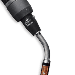
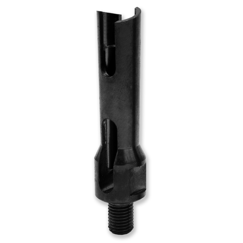
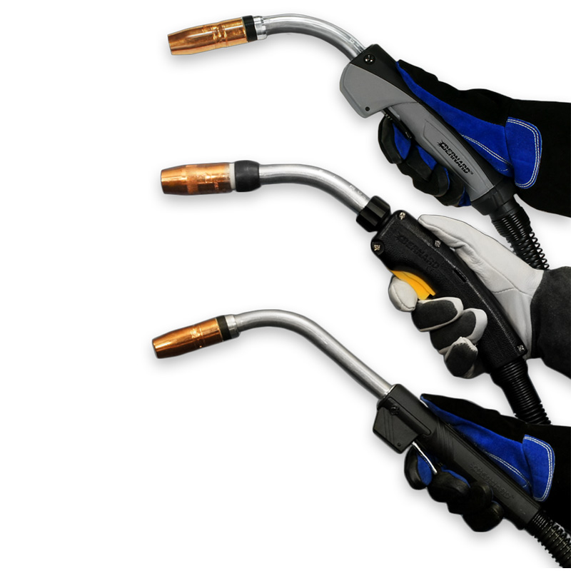
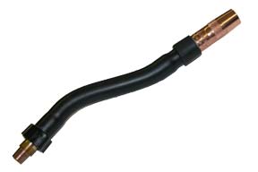
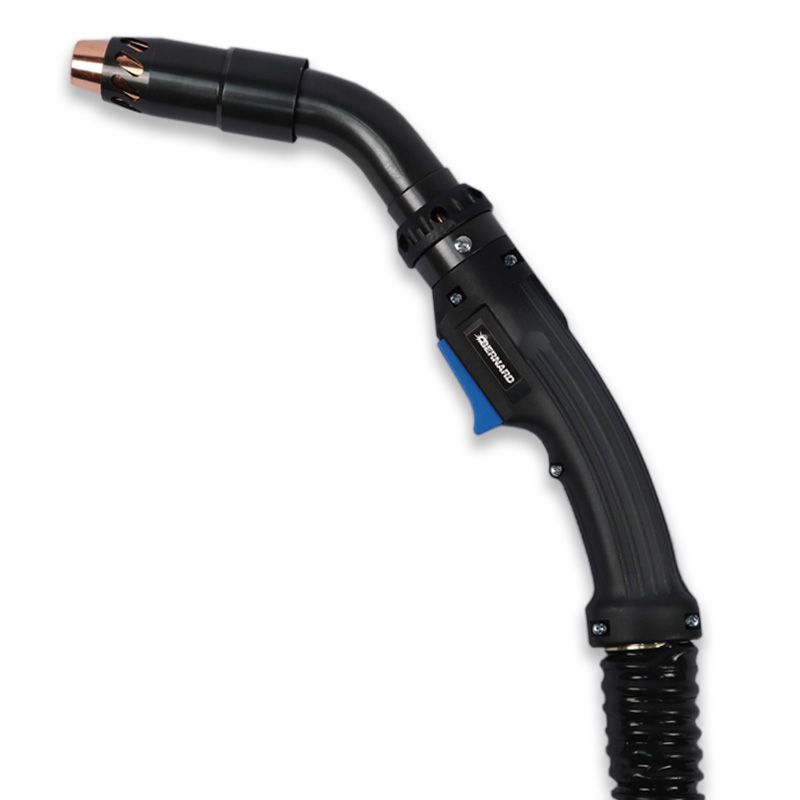
Optimizing MIG welding gun performance in specific applications can be a matter of choosing different components for the gun. Selecting the right MIG gun neck improves access to the weld joint, increases operator comfort and can reduce costs in the operation. The biggest factor when choosing a gun neck is to ensure it provides proper access and visibility to the work. In some applications, the weld joint may be difficult to reach, or it may require you to reach down into a groove. A gun neck should provide optimal access to the weld joint — so you can do your best work while maintaining proper ergonomics. In addition to joint accessibility, several other factors play a role in the decision, including the welding process and parameters, the welder’s height and whether the gun has a curved or straight handle. Keep the following considerations in mind to choose the right MIG gun neck for your application. Certain welding processes and filler metals generate much greater heat during welding, so take that into account when choosing a gun neck. Pulsed welding processes, the use of metal-cored wires and even certain materials, including stainless steel and aluminum, all generally create more heat during welding. The welding parameters — including amperage, volts, joint configuration and distance from the welder to the joint — also impact the amount of heat produced and felt by the welder. In applications with high heat, a standard short gun neck can cause the heat to radiate through the glove and into the welder’s hands. It’s recommended to use a longer gun neck in these situations to keep the heat farther away. Another good rule of thumb to remember is the larger the wire diameter being used, the longer the gun neck should be. Standard necks for MIG guns are available in a range of options, with varying angles and material types. • Aluminum armored necks can withstand abuse and offer outstanding heat dissipation. They are typically available in fixed and rotatable styles, and some models require no tools to rotate. These necks, which come in 30-, 45-, 60- and 80-degree angle options, are a good all-purpose choice for many welding applications. • Black polymer armored necks, available in a 60-degree angle, contain a thick copper wall with a conductor tube interior, so they don’t radiate or reflect heat as quickly. This insulation from the heat makes them a good choice for higher-amperage welding applications. Be aware that black polymer armored necks can become brittle and break since the high temperatures, over time, can break down the exterior tube. Choosing between these standard neck options is often a balance of application requirements and welder preference. The same is true for choosing a neck angle. The style of the gun handle, however, is also a determining factor in selecting the right neck angle. When using a curved handle, it’s often more comfortable to use a 60-degree neck than a 45-degree neck. With a straight handle, a 45-degree neck is typically better suited due to natural hand placement. A welder’s height also impacts proper neck angle: A taller welder may want to use a 60-degree neck, while a shorter welder may prefer a 45-degree neck for comfort. A neck coupler is an accessory that allows a flex neck to be added to the top of an existing standard neck. This can be used when a longer neck with flexibility is needed to get into hard-to-reach areas or narrow areas. Some flex necks have a bend radius up to 80 degrees. These necks are typically available in 6- and 8-inch lengths for straight and curved handles. Because flex necks can be changed, rotated or bent without tools, this saves time and labor. In applications where a standard neck can’t provide proper access to the weld joint, consider using a flex neck, which can be bent into a desired shape or angle to access hard-to-reach areas. Some flex necks can also be used with an easily removable jump liner for quick changeover. Jump liners replace only the most commonly worn and clogged liner area in the neck bend, to reduce downtime for liner changeover. A jump liner connects the standard liner at the back of the neck and runs through the neck up to the contact tip. Because a jump liner allows for quick and easy neck change-out, the gun can be easily adapted to fit multiple applications. For example, flex necks and rotatable necks are frequently used in shipbuilding. A welder may be in the ship’s hull and need multiple neck styles to access different weld joints. Instead of bringing several welding guns to the work area, a jump liner allows the welder to quickly unscrew one neck and thread another one on without changing or trimming the liner. An operation can also reap cost savings, since jump liners are less expensive than standard liners and quicker to install. When available standard or flex necks don’t provide proper weld joint access, specialty necks can be created. Multiple lengths and bends are available for limited access positions and improved operator comfort. These necks are specially designed by manufacturers to fit the specifications of the application. Because producing a quality weld hinges on optimal access to the joint, in some cases a custom neck can provide the best accuracy and results. Many neck options are available for MIG welding guns, including rotatable, flex, various bend angles and lengths, neck couplers and custom necks. Choosing the right style can improve your comfort and maneuverability — especially with hard-to-access welds. When you’re unable to reach your weld joints comfortably using a standard neck, consider adding a specialty or custom neck to your toolkit.
Limiting exposure to welding fumes is an increasingly important issue for many welding operations, as it provides a cleaner, more comfortable work environment and helps companies stay compliant with changing regulations. The Occupational Safety and Health Administration (OSHA) and other safety regulatory bodies set the allowable exposure limits for weld fumes and other particulates, including hexavalent chromium, with the aim of protecting employees against potential health hazards in the workplace. Some companies may choose a centralized fume extraction system designed to protect the entire shop area. However, these systems can be a substantial investment and often require installation of new ductwork. In some welding applications, they are not a feasible or efficient fume extraction option. A fume extraction gun is a viable alternative in certain welding applications, including when the welder is in a tight or confined space or must move often to complete welds on a large part. Welding guns with built-in fume extraction are commonly used in heavy industrial welding, such as truck and trailer, rail car and heavy equipment manufacturing. Fume extraction welding guns capture the fumes generated by the welding process right at the source, over and around the weld pool, and they can be tailored to best meet the needs of a specific application or to welder preferences. Consider these key factors to help choose the right type of fume extraction gun for the job — and learn more about available features that can help improve gun flexibility and performance in certain applications. Fume extraction guns are available in a variety of amperages and handle designs. Common amperages for fume extraction guns range from 300 to 600. Keep in mind that amperage is tied to gun weight. The higher the amperage, the more copper required in the power cable and therefore the heavier the gun will be. Due to this additional weight, use the lowest amperage gun possible that will still allow the job to be completed. Along with the added weight, higher-amperage guns typically cost more than lower-amperage guns, so it may be a waste of money to buy more gun than necessary for the application. However, automatically buying the lightest gun available may not provide the amperage or durability needed for the application. Some lighter and more flexible guns aren’t durable enough for heavy industrial applications. Always consider a gun’s duty cycle rating, and keep in mind that it’s a balancing act between gun weight and durability when choosing a fume extraction gun. Some fume extraction guns on the market offer features and capabilities that help optimize fume capture while also providing benefits for operator comfort and ergonomics, gun performance and ease in producing quality welds. When choosing and configuring a fume extraction gun, consider these options: The nozzle on the front of most fume extraction guns is covered by a vacuum chamber. While vacuum chambers on some guns are fixed in place, others like those on the Bernard® Clean Air E™ MIG Gun feature adjustable designs that can be moved to several positions. This provides better joint access and visibility and helps welders dial in vacuum flow to eliminate porosity. When paired with a high-performance fume extraction system like the Miller® FILTAIR® 215, these features help maximize capture efficiency and weld quality. Adjustable vacuum chambers can also improve ergonomics by reducing the need for welders to work in uncomfortable positions. Snap-in-position designs offer more durability than friction-fit styles, which can loosen or fall off over time, potentially requiring replacement. Some gun manufacturers also offer vacuum chamber variations—such as short chamber options—to further improve access and visibility. Most fume extraction guns offer a way for welders to control the vacuum suction and optimize gas flow. Look for a gun with a vacuum regulator — often positioned at the front of the handle — that allows welders to balance suction with shielding gas flow to protect against porosity. A vacuum hose designed to be crush- and snag-resistant eliminates the need for a protective hose cover in many applications. This helps reduce overall gun weight and increases flexibility of the hose. However, be aware that some heavy-duty welding applications requiring extremely high heat will always need a leather cover to protect the hose. Note, a gun with a vacuum hose that swivels also improves flexibility, visibility and joint access and helps reduce wrist fatigue. Tailoring the gun handle and neck to the application and welder preferences can help improve weld access and reduce operator fatigue. Some brands of guns are available in curved and straight handle options. In higher-amperage applications, welders may want to put the gun cable over their shoulder with the gun trigger on the top. Straight handle guns allow for this because the trigger can be positioned on the top. Some fume extraction guns also have additional neck options in a variety of bend angles, such as 30, 45 and 60 degrees. This provides even more ability to tailor a gun to specific needs and improves ergonomics. When choosing a gun with a straight handle, consider one with a rubber overmold on the handle to help reduce vibration and provide a better grip. As with any fume extraction equipment, proper use and maintenance of fume extraction guns is important to achieve optimal results. Operating a fume extraction gun is similar to using a standard MIG gun, with many of the same recommended best practices. However, there are some techniques that welders can follow to help get the best performance from a fume extraction gun: Some fume extraction guns are designed using a common consumable platform, which means any consumables used on a standard MIG gun or even a robotic MIG gun can also be used on a fume extraction gun. When fume gun replacement parts — nozzles, contact tips and gas diffusers — can be the same as those used on standard MIG guns, this offers greater flexibility and helps reduce a company’s consumables inventory. Additionally, it may be important for some companies to choose a fume extraction gun that is compatible with vacuum systems from most major manufacturers. In the right applications, fume extraction guns can help companies maintain compliance with safety regulations and create a cleaner, more comfortable welding environment for employees. When choosing fume extraction guns for MIG welding, look for features and accessories that will provide additional flexibility, time savings and advantages for welder comfort.
July 19, 2018 Tregaskiss is pleased to announce that the TOUGH GUN® TA3 robotic air-cooled MIG gun offering has now been expanded to include configurations for the FANUC® 100iD robot model. Click here to learn more about the TOUGH GUN TA3 robotic air-cooled MIG gun.
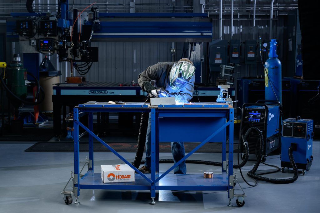
BEECHER, Ill./WINDSOR, Ontario. July 17, 2018 – Bernard and Tregaskiss announced the companies will showcase their products at FABTECH 2018 in Atlanta from November 6 to 8 in booth C12828. Bernard semi-automatic MIG guns and consumables will be on display and also featured in live welding demonstrations with power sources from Miller Electric Mfg. LLC. Tregaskiss will showcase its robotic MIG guns, consumables and peripherals and feature them in Miller pre-engineered automated welding cells. Welding demos will feature Hobart filler metals. The companies will have representatives available to answer questions and plans to unveil new products for the fabrication and manufacturing industries.
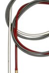
A MIG gun liner is an important consumable because it can make a significant difference in gun performance and the time and money an operation spends in unplanned downtime. Proper installation of the liner is critical to its ability to guide the wire through the welding cable and up to the contact tip. Improper liner installation — which includes trimming the liner too short or having a liner that is too long — can result in a number of problems, such as birdnesting, wire feeding issues and increased debris in the liner. These issues can result in costly rework and operator downtime for maintenance and repairs, which impacts productivity. Also, wasted wire due to issues like birdnesting can drive up costs for a company. The installation process is somewhat similar for all types of MIG gun liners, with some variations. Here are some general steps to consider when installing a new MIG gun liner. There are some variances in the installation process, depending on the type of liner being used. Follow these steps when installing a front-loading liner. The only difference in this installation process is that there is no receiver in the back of the power pin. The receiver is built into the module pin. The installation process also varies when retrofitting a gun from a conventional liner to a front-loading liner. Here are a few additional things to remember: The quality of the liner also can impact welding performance, productivity and operator downtime, so it’s important to buy quality liners from a trusted manufacturer. Choosing the correct size of liner for the wire being used is another way to help maximize performance. While liners may seem like a small part of the welding operation, it’s important to be mindful of the impact they can have on quality, performance and costs. Liners perform a vital function in the MIG welding process, and the proper installation and maintenance of liners can help reduce costly rework, operator downtime and wasted wire.
BEECHER, Ill., April 3, 2018 – Bernard has announced changes to its fume extraction gun offering. Effective immediately, Bernard® FILTAIR™ fume extraction MIG guns are transitioning to the Bernard Clean Air™ brand name and will become Bernard Clean Air curved handle series fume extraction MIG guns. In addition, several upgrades have been made to the former FILTAIR fume extraction guns. “This transition offers improved functionality, performance and ease of maintenance to our fume extraction guns — to bring flexibility and value to users,” said Jerome Parker, product manager, Bernard. Designed to produce a cleaner, more compliant work environment, Clean Air fume extraction guns are ideal for large weldments and confined space welding applications, and they range in models from 300 to 600 amps. The name change was made due to feature and performance similarities between the two gun offerings. In addition, several upgrades from the Clean Air gun line are now available for the former FILTAIR gun models, including: • Reduced overall weight, stemming from the eliminated need for a protective cover thanks to a new high-performance, crush- and snag-resistant extraction hose. • Adjustable nozzle shroud with a front vacuum chamber that adjusts to one of four positions for optimized fume capture, gas flow and weld access. • Additional neck options of 30-, 45- and 60-degrees are now available for the curved handle model. • Inclusion in the Clean Air gun online configurator with expanded options. The curved handle guns are now available with Centerfire™, Quik Tip™ and TOUGH LOCK® consumables and are compatible with QUICK LOAD® liners and the QUICK LOAD liner AutoLength™ system. Along with the name change, the FILTAIR gun part numbers have been converted to Clean Air gun part numbers for a seamless transition. Legacy products can be identified from updated products by visible changes in neck and shroud color. The fume extraction components that previously were chrome now have a black finish. Learn more about Clean Air fume extraction MIG guns, or configure you gun today.
MIG Welding FAQs Answered
MIG Welding FAQs Answered
Pair gas- or self-shielded wires with V-knurled drive rolls. These welding wires are soft due to their tubular design; the teeth on the drive rolls grab the wire and pushes it through the feeder drive. Use U-groove drive rolls for feeding aluminum welding wire. The shape of these drive rolls prevents marring of this soft wire. V-groove drive rolls are the best choice for solid wire.
To set the drive roll tension, first release the drive rolls. Slowly increase the tension while feeding the wire into your gloved hand. Continue until the tension is one half-turn past wire slippage. During the process, keep the gun as straight as possible to avoid kinking the cable, which could lead to poor wire feeding.
Following some key best practices related to welding wire, drive rolls and shielding gas can help ensure good results in the MIG welding process.
Stickout is especially important to gaining optimal results. Too long of a stickout creates a colder weld, drops the amperage and reduces joint penetration. A shorter stickout usually provides a more stable arc and better low-voltage penetration. As a rule of thumb, the best stickout length is the shortest one allowed for the application.
Proper welding wire storage and handling is also critical to good MIG welding results. Keep the spool in a dry area, as moisture can damage the wire and potentially lead to hydrogen-induced cracking. Use gloves when handling the wire to protect it from moisture or dirt from your hands. If the wire is on the wire feeder, but not in use, cover the spool or remove it and place it in a clean plastic bag.
A 1/8- or 1/4-inch recess works well for welding at greater than 200 amps in spray or high-current pulse welding, when using a metal-cored wire and argon-rich shielding gases. You can use a wire stickout of 1/2 to 3/4 inches in these scenarios.
Keep your contact tip flush with the nozzle when welding less than 200 amps in short circuit or low-current pulse modes. A 1/4- to 1/2-inch wire stickout is recommended. At 1/4-inch stick out in short circuit, specifically, allows you to weld on thinner materials with less risk of burn-through or warping.
When welding hard-to-reach joints and at less than 200 amps, you can extend the contact tip 1/8 inch from the nozzle and use a 1/4-inch stickout. This configuration allows greater access to difficult-to-access joints, and works well for short circuit or low-current pulse modes.
Remember, proper recess is key to reducing the opportunity for porosity, insufficient penetration and burn-through and to minimizing spatter.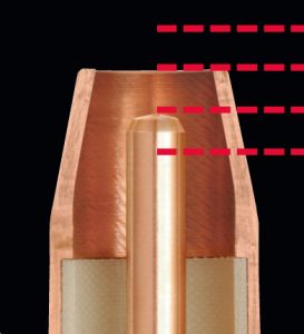
The ideal contact tip recess position varies according to the application. A general rule: As the current increases, the recess should also increase.
Use 100 percent CO2 shielding gas or a 75 percent CO2/25 percent argon mix in combination with a carbon steel solid wire. Aluminum welding wire requires argon shielding gas, while stainless steel wire works best with a tri-mix of helium, argon and CO2. Always reference the wire’s spec sheet for recommendations.
You can gauge heat input and travel speed by the weld bead produced and adjust accordingly to gain better control and better results. For example, if you produce a weld bead that is too tall and skinny, it indicates that the heat input is too low and/or your travel speed is too fast. A flat, wide bead suggests too high of heat input and/or too slow of travel speeds. Adjust your parameters and technique accordingly to achieve the ideal weld, which has a slight crown that just touches the metal around it.
These answers to frequently asked questions only touch on a few of the best practices for MIG welding. Always follow your welding procedures to gain optimal results. Also, many welding equipment and wire manufacturers have technical support numbers to contact with questions. They can serve as an excellent resource for you.PACKAGING CHANGE – Changes to Bernard Bag Packaging
PACKAGING CHANGE — Changes to Bernard Bag Packaging
Old Bernard Bags


New Bernard Bags


PACKAGING CHANGE – Changes to Tregaskiss Bag Packaging
PACKAGING CHANGES —
Changes to Tregaskiss Bag PackagingOld Tregaskiss Bags


New Tregaskiss Bags


Self-Shielded Flux-Cored Welding: Choosing Your Gun
Self-Shielded Flux-Cored Welding: Choosing Your Gun
Considering self-shielded flux-cored welding
Self-shielded flux-cored gun options

Proper maintenance, cleaning and technique
Optimizing self-shielded flux-cored welding
5 Common Failures in Robotic Welding and How to Prevent Them
5 Common Failures in Robotic Welding and How to Prevent Them
Failure No. 1: Burnback and contact tip wear
Failure No. 2: Broken cutter blades in the reamer
Other Causes for Broken Cutter Blades
Failure No. 3: Loss of tool center point
Failure No. 4: Broken discs

Failure No. 5: Incorrect tool path
Maintenance is key
DISCONTINUED PRODUCT – Tandem Robotic Torches
DISCONTINUED PRODUCTS –
Tandem Robotic MIG GunsTandem Robotic MIG Guns
Note: Availability and list prices of replacement parts for the affected products are subject to change without notice.DISCONTINUED PRODUCT – Service Parts for Quick-Change and Keyed Robotic Water-Cooled Guns
DISCONTINUED PRODUCTS –
Service Parts for Quick-Change and Keyed Robotic Water-Cooled MIG GunsService Parts for Discontinued Quick-Change Water-Cooled and Keyed Water-Cooled Robotic MIG Guns
Tregaskiss Expands Robotic MIG Welding Gun Offering
Tregaskiss Expands Robotic MIG Welding Gun Offering
Anti-Spatter Sprayer: How to See the Best Results
Anti-Spatter Sprayer: How to See the Best Results
Follow these best practices for anti-spatter liquid usage
The spray containment unit also collects anti-spatter liquid runoff so it can be easily drained into a container and disposed of in accordance with federal, state and local environmental control regulations. Anti-spatter liquid cannot be reused.
Learn more about anti-spatter liquid and available accessories.
This article is the third in a three-part series focused on the use and benefits of anti-spatter liquid. Read article one, Spatter in Welding: Should You Consider Anti-Spatter Liquid? and article two, How to Select and Use Anti-Spatter Liquid.How to Select and Use Anti-Spatter Liquid
How to Select and Use Anti-Spatter Liquid
• Easy cleanup and no residue
• Compatibility with the nozzle cleaning station or reamer being usedSafety Tips
Consider these tips:Spatter in Welding: Should You Consider Anti-Spatter Liquid?
Spatter in Welding: Should You Consider Anti-Spatter Liquid?
What is anti-spatter liquid?
• Lowers cost for consumable inventory and management
• Reduces operating costs by improving weld quality and lowering reworkDoes my operation need to use anti-spatter liquid?
Save Money, Improve Performance with Bernard Replaceable MIG Gun Parts | Customer Testimonial
Save Money, Improve Performance with Bernard® Replaceable MIG Gun Parts
Bernard MIG Welding Consumables Save Time and Last Longer | Customer Testimonial
Bernard® MIG Welding Consumables Save Time and Last Longer
New HDP Contact Tips Provide Robotic Pulsed MIG Welding Benefits
New HDP Contact Tips Provide Robotic Pulsed MIG Welding Benefits

Demands of GMAW-P

Contact tip advancements
Significant productivity gains

Additional benefits
Return on investment
Be sure to look at the big picture in terms of productivity and efficiency improvements for the entire operation.Improve productivity and efficiency
Ethernet vs. Standard Reamer: Making the Selection
Ethernet vs Standard Reamer: Making the Selection

Standard versus Ethernet
A standard reamer features inputs and outputs that are plugged into a Program Logic Controller (PLC), including the inputs that control the nozzle clamping, cutter actions and anti-spatter spray process.Robotic reamer accessories

Extra: Reamer maintenance
PRODUCT UPDATE – TOUGH GUN TA3 MIG Guns Now Compatible with More Robot Models
PRODUCT UPDATE —
TOUGH GUN TA3 MIG Guns Now Compatible with More Robot Models
Available Resources
7 MIG Welding Mistakes and How to Avoid Them
7 MIG Welding Mistakes and How to Avoid Them

No. 1: Improper liner length
No. 2: Overheated consumables

No. 3: A bad ground
No. 4: Improper voltage or wire feed speed
No. 5: Poor cable management

No. 6: Selecting the wrong gun

No. 7: Drive roll issues
Proper maintenance is also key
What MIG Gun Neck is Right for You?
What MIG Gun Neck is Right for You?

Feeling the heat
Standard necks

Neck Coupler
Flex necks
Specialty necks
Final thoughts
Fume Extraction Gun: Features and Techniques to Improve Performance
Fume Extraction Gun: Features and Techniques to Improve Performance
Fume extraction gun options
Features to consider

Adjustable vacuum chamber:
Suction control valve:
Flexible, crush- and snag-resistant hose:
Handle and neck options:
Fume extraction gun best practices
Getting results
PRODUCT UPDATE – TOUGH GUN TA3 MIG Gun Offering Available for FANUC 100iD
PRODUCT UPDATE —
TOUGH GUN TA3 MIG Gun Offering Available for FANUC 100iD Robot Model

Features & Benefits


Part Numbers
560-600 Solid Mount Connector, air-cooled, no options 560-600I Solid Mount Connector, TOUGH GUN I.C.E., no options 560-600W-045 Solid Mount Connector, air-cooled, wire brake 0.030″-0.045″ 560-600W-116 Solid Mount Connector, air-cooled, wire brake 0.052″-1/16″ 560-600IW-045 Solid Mount Connector, TOUGH GUN I.C.E., wire brake 0.030″-0.045″ 560-600IW-116 Solid Mount Connector, TOUGH GUN I.C.E., wire brake 0.052″-1/16″ 58SF011 LSR Unicable, air-cooled, no options 58SF011W LSR Unicable, air-cooled, wire brake 58SF211 LSR Unicable, TOUGH GUN I.C.E., no options 58SF211W LSR Unicable, TOUGH GUN I.C.E., wire brake 560-500A Optional Air Blast Kit for guns equipped with Lincoln® power pins
Available Resources
Bernard and Tregaskiss to Display Products, Host Live Welding at FABTECH 2018
Bernard and Tregaskiss to Display Products, Host Live Welding at FABTECH 2018
Steps for Proper MIG Gun Liner Installation
Steps for Proper MIG Gun Liner Installation
Step-by-step installation

That way, once all of the consumables are back on at the front of the gun, the wire is already in the gun and ready to be pulled through.
Installing a front-loading QUICK LOAD Liner

1. Unravel the liner (which comes coiled) and stick the brass end — the end that goes into the receiver at the back of the gun — over the wire and through the neck.
2. Feed the liner through the front of the gun using short strokes, to avoid kinking the liner. The front-loading liner will click or snap into place once it hits the receiver in the power pin.
3. Once that is complete, put the liner gauge on top of the liner and follow the standard installation steps above.Installing a front-loading liner with the spring-loaded module
Retrofitting a gun
Proper liner installation can help optimize performance
Fume Extraction MIG Gun Offering Expands, Adds Improved Features
Fume Extraction Gun Offering Expands, Adds Improved Features
![]()